background image

Installation Note E4411–90047

 3

E4411-60021 Power Supply Upgrade

Introduction

This kit has been provided to reduce excess noise in the power supply of the ESA-L1500A spectrum
analyzer.

Installation Kit Parts List

Table 1

Parts Kit E4411-60021 Contents

Product Affected: . . . . . . . . . . . . . . . . . . . . . . . .

ESA-L1500A Spectrum Analyzer

Serial Numbers:  . . . . . . . . . . . . . . . . . . . . . . .

US37451286 and Below Require This Upgrade
The Following Exceptions Do Not Require
This Upgrade:
US37451120, US37451121, US37451122,
US37451123, US37451124, US37451143,
US37451203, US37451212, US37451223,
US37451229, US37451230, US37451238,
US37451243, US37451253, US37451256,
US37451261, US37451263, US37451264,
US37451266, US37451268, US37451270,
US37451272, US37451277, US37451279,
US37451281, US37451284

To Be Performed By: . . . . . . . . . . . . . . . . . . . .

(X) Agilent Technologies Service Center
(X) Personnel Qualified by Agilent

Estimated Installation Time: . . . . . . . . . . . . .

1.25 Hours

Estimated Verification Time: . . . . . . . . . . . . .

0.5 Hour

Item

Quantity

Description

Part Number

1

1

Daughter Board

E4401-60090

2

1

Capacitor, 4700 pF, 100V (small bubble cap. labeled

472K

)

0160-4831

3

1

Capacitor, 4700 pF, 250V (rectangular cap. labeled

4n7 Y2

)

0160-4439

4

1

Capacitor, 1000 pF, 100V (small bubble cap. labeled

102K

)

0160-4574

5

2

Resistor, 10 ohm

0757-0346

6

1

Resistor, 1 ohm

0698-8812

7

1

Insulation Sleeve

0890-0099

8

1

Label, Power Supply Assembly (E4401-60111)

7121-7526

9

1

Label, Power Supply Main Power Board (E4401-60103)

9320-6209

10

1

Installation Note

E4411-90047

Summary of Contents for E4411-90047

Page 1: ...Part Number E4411 90047 Supersedes E4411 90042 Printed in USA June 2000 Installation Note Agilent Technologies ESA L1500A Spectrum Analyzer Power Supply Upgrade Kit Number E4411 60021 ...

Page 2: ...to this material including but not limited to the implied warranties of merchantability and fitness for a particular purpose Agilent Technologies shall not be liable for errors contained herein or for incidental or consequential damages in connection with the furnishing performance or use of this material Copyright 1998 2000 Agilent Technologies Inc ...

Page 3: ...37451263 US37451264 US37451266 US37451268 US37451270 US37451272 US37451277 US37451279 US37451281 US37451284 To Be Performed By X Agilent Technologies Service Center X Personnel Qualified by Agilent Estimated Installation Time 1 25 Hours Estimated Verification Time 0 5 Hour Item Quantity Description Part Number 1 1 Daughter Board E4401 60090 2 1 Capacitor 4700 pF 100V small bubble cap labeled 472K ...

Page 4: ...m all voltage sources before opening covers WARNING The spectrum analyzer contains potentially hazardous voltages Failure to heed the safety precautions can result in severe or fatal injury CAUTION Electrostatic discharge ESD can damage or destroy electronic components All work on electronic assemblies should be performed at a static safe workstation Refer to the documentation that pertains to you...

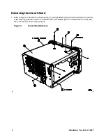
Page 5: ... front frame facing down Refer to Figure 2 3 Remove the four screws 1 that hold the rear frame 2 and outer case 4 in place 4 Pull the instrument outer case and rear frame off toward the rear of the instrument CAUTION The Rear EMI Gasket 3 that clips onto the rear panel can come loose Note the correct position to reattach the gasket Figure 2 Outer Case Rear Frame Removal ...

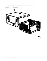
Page 6: ...1 Refer to Figure 3 Remove the 16 screws 2 3 and 4 attaching the inner shield 1 to the chassis If the tracking generator option is installed the screw labeled 4 will not be present In that case there will be only 15 screws 2 and 3 Figure 3 Inner Shield Removal ...

Page 7: ...Installation Note E4411 90047 7 2 Refer to Figure 4 The inner shield 1 can now be removed from the chassis Figure 4 Inner Shield ...

Page 8: ...on the bottom side of the instrument that secure the front frame to the RF assembly 2 Place the instrument with the top side facing up Remove the two screws 2 that secure the front frame subpanel to the chassis 3 Slide the front frame 4 forward until it catches on the tabs 3 on the sides of the chassis Figure 5 Front Frame Assembly Removal ...

Page 9: ... rotating upward The support can be removed by sliding it out of the holes in each assembly CAUTION If forced the vibration support can be broken remove with care 2 Remove the single screw 3 securing the A5 power supply assembly 4 to the chassis at the rear of the instrument 3 Carefully pull up on the power supply assembly to remove it from the motherboard connector Figure 6 Vibration Support ...

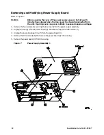
Page 10: ...m the unit Opening covers any soon is likely to expose dangerous voltages 1 Remove the four screws 1 securing the top cover 2 to the power supply assembly 2 Unplug the fan 5 from the power board 3 Remove the top cover with the fan 2 3 Unplug the incoming power line 7 from the power board 3 4 Remove the three screws 6 that secure the power board 3 to the casing 5 Remove the power board 3 from the c...

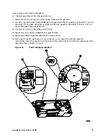
Page 11: ... board solder the 4700 pF capacitor 0160 4831 from pin 2 of T1 to the cathode pad square pad of CR43 9 Unsolder and remove C86 R238 and C174 3 10 Solder the 1 ohm resistor 0698 8812 in place of R238 11 Solder the 1000 pF capacator 0160 4574 in place of C86 12 Place two 90 bends as shown in Figure 8 at 2 in one lead of the 4700 pF capacitor 0160 4439 Insert the capacitor into the board in the place...

Page 12: ...trument Line up the tabs on the support with the holes in each assembly and the rear blank panel Slide the support sideways into the holes then rotate down until the ends clip into the power supply and the IF assemblies Replacing the Front Frame 1 Carefully slide the front frame toward the chassis assuring the ribbon cable is not pinched between assemblies and the RF input connector lines up corre...

Page 13: ...r frame loosen all the rear card cage screws power supply screw IF screws and option card screws and move the whole group of parts in the direction needed to ensure that the fingers of the gasket make contact with the rear panels If the panels are properly aligned but the EMI fingers do not reach the panels remove the rear frame and bend the fingers farther out to ensure that they make contact wit...

Reviews: