12
Operation and Service Guide
General Information
suring the “Power level used as reference” and the “Power level being mea-
sured.” This chart illustrates that the best relative power measurement
accuracy is obtained when the reference and the measured power levels are
equal to, or less than,
−
20 dBm. Care in choosing the power levels can yield
improved measurement accuracy. Example A illustrates a relative gain
(amplifier measurement) and example B illustrates a relative loss (insertion
loss measurement).
EXAMPLE A (Amplifier Gain Measurement):
Input power (reference) =
−
35 dBm; power measured = +6 dBm, so the rela-
tive gain is +41 dB. The chart indicates a typical error of
±
6%, which corre-
sponds to +0.25 dB/
−
0.27 dB uncertainty in the gain measurement.
EXAMPLE B (Insertion Loss Measurement):
Reference power =
−
25 dBm; power measured =
−
35 dBm, for the case of an
insertion loss of 10 dB. The chart indicates a typical error of
±
1%, which
corresponds to
±
0.04 dB uncertainty in the measurement.
Calibration Factor (CF) and Reflection Coefficient (Rho)
Calibration factor and reflection coefficient data are given at 1 GHz incre-
ments on a data sheet included with the power sensor. This data is unique to
each sensor. If you have more than one sensor, match the serial number on
the data sheet with the serial number on the power sensor you are using. The
CF corrects for the frequency response of the sensor. The power meter auto-
matically reads the CF data stored in the sensor and uses it to make the cor-
rections.
Reflection Coefficient (Rho, or
ρ
) relates to SWR according to the following
formula:
SWR = (1+
ρ
)/(1-
ρ
)
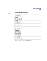
Maximum uncertainties of the CF data are listed in Table 2 for the E4412A
power sensor, and in Table 3 for the E4413A power sensor. The uncertainty
analysis for the calibration of the sensors was done in accordance with the
ISO/TAG4 Guide. The uncertainty data reported on the calibration certifi-
cate is the expanded uncertainty with 95% confidence level and a coverage
factor of 2.


