background image

Contents

Agilent Technologies E4416A/E4417A Power Meters Service Guide

xiii

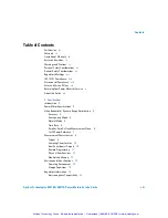
Table of Contents

Certification

iii

Warranty

iii

Limitation of Warranty

iv

Exclusive Remedies

iv

Warnings and Cautions

iv

Personal Safety Considerations

vi

General Safety Considerations

vi

Regulatory Markings

vii

IEC 1010-1 Compliance

viii

Statement of Compliance

viii

Sales and Service Offices

ix

Returning Your Power Meter for Service

x

About this Guide

xii

1   

Specifications

Introduction

2

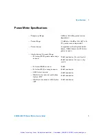
Power Meter Specifications

3

Video Bandwidth/ Dynamic Range Optimization

5

Accuracy

5

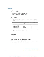
Average-only Mode

6

Normal Mode

6

Time Base

6

Zero Set, Zero Drift and Measurement Noise:

6

1 mW Power Reference

7

Measurement Characteristics

8

Trigger

9

Sampling Characteristics

10

Rear Panel Inputs/Outputs

10

Remote Programming

11

Physical Specifications

11

Non-Volatile Memory

12

Environmental Specifications

13

Operating Environment

13

Storage Conditions

13

Regulatory Information

14

Electromagnetic Compatibility

14

Artisan Technology Group - Quality Instrumentation ... Guaranteed | (888) 88-SOURCE | www.artisantg.com

Summary of Contents for E4416A

Page 1: ... underutilized and idle equipment along with credit for buybacks and trade ins Custom engineering so your equipment works exactly as you specify Critical and expedited services Leasing Rentals Demos In stock Ready to ship TAR certified secure asset solutions Expert team I Trust guarantee I 100 satisfaction All trademarks brand names and brands appearing herein are the property of their respective ...

Page 2: ...Agilent Technologies Agilent Technologies E4416A E4417A Power Meters Service Guide Artisan Technology Group Quality Instrumentation Guaranteed 888 88 SOURCE www artisantg com ...

Page 3: ...ict with these terms the warranty terms in the sep arate agreement shall control Technology Licenses The hardware and or software described in this document are furnished under a license and may be used or copied only in accor dance with the terms of such license Restricted Rights Legend U S Government Restricted Rights Soft ware and technical data rights granted to the federal government include ...

Page 4: ...t During the warranty period Agilent Technologies will at its option either repair or replace products which prove to be defective For warranty service or repair this product must be returned to a service facility designated by Agilent Technologies Buyer shall prepay shipping charges to Agilent Technologies and Agilent Technologies shall pay shipping charges duties and taxes for products returned ...

Page 5: ...GIES SHALL NOT BE LIABLE FOR ANY DIRECT INDIRECT SPECIAL INCIDENTAL OR CONSEQUENTIAL DAMAGES WHETHER BASED ON CONTRACT TORT OR ANY OTHER LEGAL THEORY Warnings and Cautions This guide uses warnings and cautions to denote hazards WARNING A warning calls attention to a procedure practice or the like which if not correctly performed or adhered to could result in injury or the loss of life Do not proce...

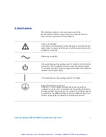
Page 6: ...Note the instrument is NOT isolated from the mains when the switch is pressed To isolate the instrument the mains coupler mains input cord should be removed from the power supply This symbol indicates the operating switch for On mode External Protective Earth Terminal While this is a Class I product provided with a protective earthing conductor in a power cord an external protective earthing termi...

Page 7: ...rts inside Refer servicing to qualified personnel To prevent electrical shock do not remove covers For continued protection against fire hazard replace the line fuse s only with fuses of the same type and rating for example normal blow time delay etc The use of other fuses or material is prohibited WARNING Before this instrument is switched on make sure it has been properly grounded through the pr...

Page 8: ...ar it signifies when the design was proven This ISM device complies with Canadian ICES 001 Cet appareil ISM est conforme à la norme NMB 001 du Canada This is the symbol of an Industrial Scientific and Medical Group 1 Class A product The CSA mark is a registered trademark of the Canadian Standards Association Artisan Technology Group Quality Instrumentation Guaranteed 888 88 SOURCE www artisantg co...

Page 9: ...must be followed by the user to ensure safe operation and to maintain the instrument in a safe condition Statement of Compliance This product has been designed and tested for compliance with IEC 60529 1989 Degrees of Protection Provided by Enclosures IP Code Level IPx4 is attained if and only if the carry case Agilent Technologies part number 34141A is fitted Recommended Calibration Interval Agile...

Page 10: ...ber With this information the Agilent Technologies representative can quickly determine whether your unit is still within its warranty period Country Phone Number Fax Number United States 800 829 4444 800 829 4433 Canada 877 894 4414 800 746 4866 China 800 810 0189 800 820 2816 Europe 31 20 547 2111 Japan 81 426 56 7832 81 426 56 7840 Korea 080 769 0800 080 769 0900 Latin America 305 269 7500 Taiw...

Page 11: ...ith 159 kg 350 lb bursting strength The carton must be both large enough and strong enough to accommodate the power meter and allow at least 3 to 4 inches on all sides of the power meter for packing material 3 Surround the power meter with at least 3 to 4 inches of packing material or enough to prevent the power meter from moving in the carton If packing foam is not available the best alternative ...

Page 12: ...ial to both protect the power meter and prevent it from moving in the carton 4 Seal the shipping container securely with strong nylon adhesive tape 5 Mark the shipping container FRAGILE HANDLE WITH CARE to ensure careful handling 6 Retain copies of all shipping papers Artisan Technology Group Quality Instrumentation Guaranteed 888 88 SOURCE www artisantg com ...

Page 13: ...disassemble the power meter 6 Troubleshooting This chapter contains troubleshooting flow charts designed to isolate faults in the Rmt I O GPIB and RS232 422 interface ports A Agilent 432A Power Meters 478A Sensors Additional Information This appendix contains additional information for Agilent 432A power meters and 478A sensors B Equipment Required For Performance Tests And Adjustments This append...

Page 14: ... xii 1 Specifications Introduction 2 Power Meter Specifications 3 Video Bandwidth Dynamic Range Optimization 5 Accuracy 5 Average only Mode 6 Normal Mode 6 Time Base 6 Zero Set Zero Drift and Measurement Noise 6 1 mW Power Reference 7 Measurement Characteristics 8 Trigger 9 Sampling Characteristics 10 Rear Panel Inputs Outputs 10 Remote Programming 11 Physical Specifications 11 Non Volatile Memory...

Page 15: ...acy Normal Path Test 21 Specification 21 Description 21 Equipment 22 Test Setup 22 Procedure 23 Instrument Accuracy Average Path Test 28 Specification 28 Description 28 Test Procedure 1 28 Equipment 28 Test Setup 29 Instrument Accuracy Average Path Test Setup 29 Test Procedure 2 32 Equipment 32 Test Setup 32 Procedure 33 Power Reference Level Test 36 Description 36 Equipment 38 Test Setup 38 Proce...

Page 16: ...50 Specification 50 Description 50 Equipment 52 Test Setup 52 Procedure 52 Performance Test Record 57 3 Adjustments Introduction 60 Safety Considerations 60 Equipment Required 60 Post Repair Adjustments 61 Power Reference Oscillator Frequency Adjustment 62 Description 62 Equipment 62 Procedure 63 Power Reference Oscillator Level Adjustment 65 Description 65 Equipment 67 Procedure 68 Measurement Un...

Page 17: ...Removing the A1 Power Supply Assembly 96 Removing the A2 Processor Assembly 97 Removing the A4 Comms Assembly 99 Removing the A5 Daughter or A6 Measurement Assemblies 101 Removing the A7 Fan Assembly 102 Removing the Power Meter RAM Battery BT1 103 Removing the A3 Front Panel Assembly 105 Replacing the Front Panel Power Sensor Cable Assemblies 106 Replacing the Front Panel Power Reference Cable As...

Page 18: ...and C 136 Define the Measurement Equation C 136 Uncertainty Equation C 139 Voltage Measurements Uncertainty C 139 Mismatch C 141 Calibration factor C 142 Sensor Calibration Factor Drift C 143 Resistance C 143 Repeatability C 144 Sensitivity Coefficients Ci C 146 Combined Standard Uncertainty uc y C 148 Expanded Uncertainty C 148 D Measurement Uncertainty Analysis Instrument Accuracy Test Measureme...

Page 19: ...xviii Agilent Technologies E4416A E4417A Power Meters Service Guide Contents Artisan Technology Group Quality Instrumentation Guaranteed 888 88 SOURCE www artisantg com ...

Page 20: ... Accuracy Test Setup 48 Figure 3 1 Adjustment Setup 62 Figure 3 2 A2L9 Adjustment Location 64 Figure 3 3 Adjustment Setup 66 Figure 3 4 A2R90 Adjustment Location 70 Figure 6 1 Troubleshooting Guide TTL Output 1 118 Figure 6 2 Troubleshooting Guide TTL Output 1 continued 119 Figure 6 3 Troubleshooting Guide TTL Output 2 120 Figure 6 4 Troubleshooting Guide TTL Output 2 continued 121 Figure 6 5 Trou...

Page 21: ... 35 Table 2 5 Power Reference Level Test Result 40 Table 2 6 Functional Test Average Path Results 46 Table 2 7 Power Reference Level Test Result 49 Table 2 8 Output SWR Result 56 Table 2 9 Performance Test Record 57 Table 3 1 Post Repair Adjustments Tests and Checks 61 Table B 1 Equipment Required For Performance Tests And Adjustments B 132 Table C 1 Measurement Repeatability Results C 144 Table C...

Page 22: ...ations Introduction 2 Power Meter Specifications 3 Video Bandwidth Dynamic Range Optimization 5 Measurement Characteristics 8 Environmental Specifications 13 Regulatory Information 14 Artisan Technology Group Quality Instrumentation Guaranteed 888 88 SOURCE www artisantg com ...

Page 23: ...uncertainty calculations refer to Agilent Application Note 64 1 Fundamentals of RF and Microwave Power Measurements Literature Number 5965 6630E Compatibility the EPM P Series power meters operate with the E Series E9320 family of power sensors for peak average and time gated measurements The EPM P Series meters also operate with existing 8480 Series N8480 Series E Series E4410 and E9300 ranges of...

Page 24: ...0 Series and E Series power sensors Single Sensor Dynamic Range E Series E9320 peak and average sensors E Series E4410 sensors E Series E9300 average sensors 8480 Series sensors N8480 Series sensors excluding Option CFT N8480 Series sensors with Option CFT 70 dB maximum Normal mode 85 dB maximum Average only mode 90 dB 80 dB maximum 50 dB maximum 55 dB maximum 50 dB maximum Artisan Technology Grou...

Page 25: ... 3 digits in linear mode 100 dB in 0 001 dB increments to compensate for external loss or gain 5 MHz set by meter and is sensor dependent NOTE The video bandwidth represents the ability of the power sensor and meter to follow the power envelope of the input signal The power envelope of the input signal is in some cases determined by the signal s modulation bandwidth and hence video bandwidth is so...

Page 26: ...rmation on the sensor s peak flatness response A filter Off mode is also provided Accuracy Instrumentation Add the corresponding power sensor linearity percentage Refer to the Specifications section in the user s guide supplied with your power sensor Table 1 1 Video Bandwidth vs Peak Power Dynamic Range Sensor Video Bandwidth Maximum Peak Power Dynamic Range Off High Medium Low E9321A 300 kHz 300 ...

Page 27: ...easurement Noise For E Series E9320 sensors refer to the Specifications Section in the E Series E9320 Power Sensors Operating and Service Guide Calibration Temperature1 5 ºC Temperature 0 to 55 ºC Absolute accuracy log 0 04 dB 0 08 dB Absolute accuracy linear 0 8 1 7 Relative accuracy log 0 08 dB 0 16 dB Relative accuracy linear 1 6 3 4 1 Power meter is within 5 ºC of its calibration temperature A...

Page 28: ...nternational des Poids et Mesures Mutual Recognition Arrangement Further information is available from the the Bureau International des Poids et Mesures at http www bipm fr Power Output 1 00 mW 0 0 dBm Accuracy for two years 0 9 0 to 55 o C 0 6 25 10 o C 0 5 23 3 oC Frequency 50 MHz nominal SWR 1 06 maximum 1 08 maximum for Option 003 Connector Type Type N f 50 Ω Artisan Technology Group Quality I...

Page 29: ...nsor Type Measurement Speed readings per second Normal x1 Fast1 2 E Series E9320 peak and average sensors Average only mode 20 40 400 Normal mode3 20 40 1000 E Series E4410 and E Series E9300 average power sensors 20 40 400 8480 Series power sensors 20 40 N A N8480 Series power sensors 20 40 N A 1 Fast speed not available for 8480 Series and N8480 Series sensors 2 Maximum measurement speed is obta...

Page 30: ...for delays 50 ms otherwise 200 ns Hold off Range 1 μs to 400 ms Resolution 1 of selected value minimum of 100ns Internal Trigger Range 20 to 20 dBm Level Accuracy 0 5 dB Resolution 0 1 dB Latency 500 ns 100 ns Latency is defined as the delay between the applied RF crossing the trigger level and the power meter switching into the triggered state External Trigger Range High 2 0 V Low 0 8 V BNC conne...

Page 31: ...ined limit TTL Input initiates zero and calibration routine Connector type RJ 45 Series shielded modular jack assembly TTL Output high 4 8 V max low 0 2 V max TTL Input high 3 5 V min 5 V max low 1 V max 0 3 V min RS 232 422 Interface Serial interface for communication with an external controller Male Plug 9 pin D subminiature connector Trigger In Accepts a TTL signal for initiating measurements B...

Page 32: ...nd IEC 625 RS 232 and RS 422 interfaces are supplied as standard Command Language SCPI standard interface commands GPIB Compatibility SH1 AH1 T6 TE0 L4 LE0 SR1 RL1 PP1 DC1 DT1 C0 Dimensions excluding front and rear panel protrusions 212 6 mm W 88 5 mm H 348 3 mm D 8 5 in 3 5 in 13 7 in Weight Net E4416A 4 0 Kg 8 8 lb approximately E4417A 4 1 Kg 9 0 lb approximately Weight Shipping E4416A 7 9 Kg 17...

Page 33: ...A E4417A Power Meters Service Guide Non Volatile Memory Battery Lithium Polycarbon Monoflouride approximate lifetime 5 years at 25 o C Artisan Technology Group Quality Instrumentation Guaranteed 888 88 SOURCE www artisantg com ...

Page 34: ...Maximum Humidity 95 at 40 o C non condensing Minimum Humidity 15 at 40 o C Maximum Altitude 3 000 meters 9 840 feet Storage Temperature 20 o C to 70 o C Non Operating Maximum Humidity 90 at 65 o C non condensing Non Operating Maximum Altitude 15 240 meters 50 000 feet Artisan Technology Group Quality Instrumentation Guaranteed 888 88 SOURCE www artisantg com ...

Page 35: ...g EMC test specifications EN 55011 1991 Group 1 Class A and EN 50082 1 1992 In order to preserve the EMC performance of the product any cable which becomes worn or damaged must be replaced with the same type and specification Product Safety This product conforms to the requirements of European Council Directive 73 23 EEC and meets the following safety standards IEC61010 1 1990 A1 1992 A2 1995 EN 6...

Page 36: ...trument Accuracy Average Path Test 28 Power Reference Level Test 36 Agilent E Series Power Sensor Interface Test 41 Agilent E932x Power Sensor Average Path Functional Test 43 Time Base Accuracy Test 47 Output Standing Wave Ratio SWR Test 50 Performance Test Record 57 Artisan Technology Group Quality Instrumentation Guaranteed 888 88 SOURCE www artisantg com ...

Page 37: ... sensor interface test Agilent E932x power sensor average path functional test Time base accuracy test Output standing wave ratio SWR test Equipment Required Each performance test description details the equipment required by the test In addition Appendix B summarizes the equipment required for all performance tests and adjustments NOTE The following conditions must be met for valid performance te...

Page 38: ...formed more frequently Test Procedures It is assumed that the person performing the tests understands how to operate the specified test equipment Equipment settings other than those for the power meter are stated in general terms It is assumed that the person will select the proper cables adapters and probes required for test setups illustrated in this chapter Thermistor Mount Option The following...

Page 39: ...0A Electrical Characteristics Performance Limits Accuracy Zero set Digital settability of zero 0 0764 mW This performance limit is determined by the zero set specification of the power sensor used in the measurement plus the measurement noise The range calibrator has a zero set specification of 0 05 mW The calibrator measurement noise specification is 110 nW at 16 averages At 512 averages a noise ...

Page 40: ...in watts 5 Set the range calibrator as follows RANGE 3 μW POLARITY NORMAL FUNCTION STANDBY LINE ON Agilent 11730A Power Meter CHANNEL A Power Meter Range Calibrator NOTE The procedure details the key presses required on the Agilent Technologies E4416A For the Agilent Technologies E4417A the equivalent key presses should be performed on both channels Preset Local Confirm Meas Display Units W Artisa...

Page 41: ...hat the power meter s reading is within 0 05 μW Record the reading Table 2 1 Zero Test Results NOTE When switching the range calibrator to STANDBY allow enough time for the range calibrator to settle to its zero value before attempting to zero the power meter This settling would appear on the power meter display as downward drift When the drift has reached minimum typically less than 60 seconds th...

Page 42: ...hen calculated using the non biased or n 1 method Equation 2 1 Standard Deviation The test result is obtained by applying a factor of K 2 58 Equation 2 2 Accuracy This accuracy figure represents electrical performance of the normal path with confidence limits of 99 Electrical Characteristics Performance Limits maximum Accuracy 0 8 or 0 04 dB σ nΣx 2 Σx 2 n n 1 Accuracy 2 58σ Artisan Technology Gro...

Page 43: ...58A Breakout box kit Agilent E9288 opt K01 comprises a breakout box coupler and a pair of interconnecting red black leads Test Setup Figure 2 2 Instrument Accuracy Normal Path Test Setup Breakout box Digital Voltmeter input black red Power sensor cable CHANNEL A Power meter Power sensor Power ref Power sensor cable input Artisan Technology Group Quality Instrumentation Guaranteed 888 88 SOURCE www...

Page 44: ...ment 6 Remove any offset errors introduced by the DVM and the breakout box kit with no power applied On the DVM press Shift Auto Zero Press five times The word math is shown on the DVM display window Press once Press eight times The words math null are shown on the DVM display window Press Enter to complete the key sequence 7 Turn on the power reference Press NOTE The procedure details the key pre...

Page 45: ...des a point of reference that allows the power meter and DVM measurements to be compared at varying power levels 11 Connect the 30 dB reference attenuator as shown in Figure 2 3 Zero Cal Cal Zero Cal Cal Cal A System More Service Self Test More Fast Path Accuracy Ref Volts at 0 0 dBm Enter NOTE When operating the power meter in this test mode the range of power levels that can be applied is 3 dBm ...

Page 46: ...Value x column of Table 2 2 16 Calculate the linear standard deviation of the data using Equation 2 1 Standard Deviation where n number of samples 50 and x calculated error values listed in the Error Value x column of Table 2 2 Figure 2 3 Test Setup With Attenuator Connected Digital Voltmeter input black red Breakout box Power Sensor Power Meter CHANNEL A Power ref Power sensor cable Power sensor ...

Page 47: ..._ _________ 32 _________ _________ _________ 8 _________ _________ _________ 33 _________ _________ _________ 9 _________ _________ _________ 34 _________ _________ _________ 10 _________ _________ _________ 35 _________ _________ _________ 11 _________ _________ _________ 36 _________ _________ _________ 12 _________ _________ _________ 37 _________ _________ _________ 13 _________ _________ ____...

Page 48: ...________ _________ _________ 49 _________ _________ _________ 25 _________ _________ _________ 50 _________ _________ _________ Table 2 2 Instrument Accuracy Normal Path Test Results Table continued Sample Number Power Meter Value DVM Value Error Value x Sample Number Power Meter Value DVM Value Error Value x Artisan Technology Group Quality Instrumentation Guaranteed 888 88 SOURCE www artisantg c...

Page 49: ...t Procedure 1 Equipment Range calibrator Agilent 11683A Power sensor cable Agilent E9288A Electrical Characteristics Performance Limits maximum Accuracy 0 5 or 0 02 dB This performance limit does not include the corresponding sensor power linearity specification NOTE The measurement uncertainty of this test procedure is relatively high at power levels of 30 μW and below as it uses a standard 11683...

Page 50: ...the instrument Press then 4 Set the display units to watts Press 5 Set the display resolution Press then press until is selected Power Meter CHANNEL A Range Calibrator Power sensor cable NOTE The procedure details the key presses required on the Agilent E4416A For the Agilent E4417A the equivalent key presses should be performed on both channels Preset Local Confirm Meas Display Units W Meas Displ...

Page 51: ...brator s FUNCTION switch to CALIBRATE 10 Set the range calibrator s RANGE switch to 1 mW 11 Calibrate the power meter Press 12 Set the range calibrator s RANGE switch to the positions shown in Table 2 3 For each setting verify that the power meter s reading is within the limits shown NOTE When switching the range calibrator to STANDBY allow enough time for the range calibrator to settle to its zer...

Page 52: ...______ _________________ 300 μW 314 40 μW 317 60 μW _________________ _________________ 1 mW 0 995 mW 1 005 mW _________________ _________________ 3 mW 3 141 mW 3 171 mW _________________ _________________ 10 mW 9 984 mW 10 08 mW _________________ _________________ 30 mW 31 63 mW 31 94 mW _________________ _________________ 100 mW 100 9 mW 101 8 mW _________________ _________________ 1 These perfo...

Page 53: ...est procedure is significantly lower than the previously described method refer to Appendix D Measurement Uncertainty Analysis Instrument Accuracy Test for a description of the measurement uncertainty analysis As such this test procedure should be used to ensure the power meter meets its published specification Figure 2 5 Instrument Accuracy Average Path Test Setup Power Meter Power sensor cable R...

Page 54: ...the DC calibrator are floating and are not connected to the earth ground 4 Switch the power meter on 5 Preset the instrument Press then 6 Set the display units to watts Press 7 Set the display resolution Press then press until is selected NOTE The following procedure should be performed for the Instrument Accuracy Test The procedure details the key presses required on the Agilent E4416A For the Ag...

Page 55: ...p window is displayed Set the filter length to 512 Press 11 Zero the power meter Press Wait approximately 10 seconds for the wait symbol to disappear 12 Set the DC calibrator output to 144 93 mV and set the output switch to NOTE When switching the range calibrator to STANDBY allow enough time for the range calibrator to settle to its zero value before attempting to zero the power meter This settli...

Page 56: ...623 μW 256 0 028 μW 3 0977 μW _____ _____ 3 2269 μW 3 1257 3 1989 1 4493 mV 10 μW 256 0 027 μW 9 904 μW _____ _____ 10 096 μW 9 931 10 069 4 5831 mV 31 6228 μW 256 0 027 μW 31 428 μW _____ _____ 31 819 μW 31 455 31 792 14 493 mV 100μW 64 0 073 μW 99 49 μW _____ _____ 100 51 μW 99 563 100 437 45 831 mV 316 2278 μW 64 0 104 μW 314 72 μW _____ _____ 317 74 μW 314 824 317 636 144 93 mV 1 mW 16 0 2 μW ...

Page 57: ...eference oscillator meets the accuracy specification of 0 5 after 2 years Electrical Characteristics Performance Limits maximum Conditions Power reference 1 mW Internal 50 MHz oscillator factory set to 0 4 traceable to National Physical Laboratory NPL UK Power reference accuracy setting 0 1 Guardbanded Test Line Limits Power reference accuracy after 2 years 0 9 0 to 55 ºC Worst case power meter ac...

Page 58: ...n criteria may vary if alternative test instruments are used In such cases refer to the manufacturer s guidelines for further information The test is performed using Equation 2 4 Equation 2 4 Power Level Provided By The Reference Oscillator The components of this equation are defined as follows V0 is the voltage measured between Vcomp and VRF with no power applied and after the Agilent 432A has be...

Page 59: ...onnector on the rear panel of the Agilent 432A and pin 1 on the thermistor mount end of the sensor cable Verify that no power is applied to the Agilent 432A Figure 2 6 Power Reference Level Test Setup Power Meter Test Power Meter VRF Vcomp Thermistor mount Power ref Digital Voltmeter input input NOTE The procedure details the key presses required on the Agilent E4416A For the Agilent E4417A the eq...

Page 60: ...6 Set the DVM to measure microvolts 7 Connect the positive and negative input leads to the Vcomp and VRF connectors respectively on the rear panel of the test power meter 8 Observe the reading on the DVM If less than 400 µV proceed to the next step If 400 µV or greater press and hold the test power meter Fine Zero switch and adjust the Coarse Zero control so that the DVM indicates 200 µV or less R...

Page 61: ...gilent 432A chassis ground 13 Observe the DVM reading Record the reading as Vcomp Vcomp ___________ 14 Calculate the Power Reference Oscillator power using equation 2 4 15 Verify that Pmeas is within the limits shown in Table 2 5 and record the reading in the table Table 2 5 Power Reference Level Test Result Min Max Actual Result 0 991 mW 1 009 mW __________________ Artisan Technology Group Qualit...

Page 62: ... This test verifies that the power meter can successfully download this data from the sensor Equipment Power sensor cable Agilent E9288A Power sensor Agilent E9321A Procedure 1 Connect the E9321A power sensor to the power meter s Channel A input The following message appears For the Agilent E4416A Reading Sensor For the Agilent E4417A Reading Sensor ChA When all data has been downloaded this messa...

Page 63: ... 1 for Channel B NOTE When no power sensor is connected to the Channel A input the following message is displayed on the measurement window For the Agilent E4416A No Sensor For the Agilent E4417A No Sensor ChA Artisan Technology Group Quality Instrumentation Guaranteed 888 88 SOURCE www artisantg com ...

Page 64: ...se power sensors the voltages presented to the power sensor connector are always within the range of voltages available from the Agilent 11683A range calibrator Equipment Power sensor cable Agilent E9288A Reference attenuator Agilent 11708A Power sensor Agilent E9321A Test Setup Refer to Figure 2 7 and Figure 2 8 below Procedure Use the following procedure to perform the test NOTE The procedure de...

Page 65: ... using the up down arrow keys Select a value of AVG only Press Press 4 Zero the instrument Press Wait approximately 25 seconds for the wait symbol to disappear 5 Press to calibrate the power meter 6 Connect the 30 dB attenuator as shown in Figure 2 8 Figure 2 7 Sensor Average Path Functional Test Setup Power Meter CHANNEL A Power Sensor Power sensor cable Power ref Preset Local Confirm Channel Cha...

Page 66: ...ge Press Move to the Range parameter using the up down arrow keys Scroll through the Range values by pressing Select a value of UPPER Press 11 Verify that the display reads 30 dBm 1 dB Record the reading in Table 2 6 12 Turn on the power reference Press Figure 2 8 Sensor Average Path Functional Test Setup With Attenuator Power Meter CHANNEL A Power Sensor Power sensor cable 30 dB attenuator Zero C...

Page 67: ...tch to the power sensor s upper range Press Move to the Range parameter using the up down arrow keys Scroll through the Range values by pressing Select a value of UPPER Press 18 Verify that the display reads 0 dBm 1 dB Record the reading Table 2 6 Functional Test Average Path Results Test Channel A Results Channel B Results Agilent E4417A Only Low Range 30 dB pad _________________ ________________...

Page 68: ...racy of the sampling rate when making measurements Time base frequency is measured by attaching a frequency counter to the Trig Out socket on the rear of the power meter then enabling test mode from the service menu Equipment Frequency counter Agilent 53132A Electrical Characteristics Performance Limits Frequency accuracy 10 MHz 0 01 Artisan Technology Group Quality Instrumentation Guaranteed 888 ...

Page 69: ...e instrument Press then 4 Enable time base test mode Press 5 Note the reading on the frequency counter and verify that it is within the limits shown in Table 2 7 Figure 2 9 Time Base Accuracy Test Setup Power Meter rear Trig out Frequency Counter Preset Local Confirm System More Service Self Test More Time Base Enable 10 MHz TB Artisan Technology Group Quality Instrumentation Guaranteed 888 88 SOU...

Page 70: ...17A Power Meters Service Guide 49 Table 2 7 Power Reference Level Test Result Min Max Actual Result 9 9990 MHz 10 0010 MHz ________________ Artisan Technology Group Quality Instrumentation Guaranteed 888 88 SOURCE www artisantg com ...

Page 71: ... This can be expressed in terms of the voltage reflection coefficients VRC as follows Equation 2 5 Power Absorbed By The Load Where PZO is the power that the source will deliver to a matched load and are the VRCs of the source and load respectively Electrical Characteristics Performance Limits maximum Output SWR 1 06 1 08 For instruments with the 50 MHz 1mW output power ref connector mounted on th...

Page 72: ...set to 100 Ω the RF impedance is 25 Ω giving a nominal of 0 33 The effective efficiency of the thermistor mount remains constant under these two conditions so that the power ratio between operation at 200 Ω and 100 Ω can be accurately measured If the two reflection coefficients are and and these give the power measurements of P1 and P2 respectively but the available power remains the same then the...

Page 73: ...tely accurate results provided the phase angle of the source is within 40o of 0o or 180o Equipment Test power meter Agilent 432A Thermistor mount Agilent 478A Option H75 or H76 Digital voltmeter DVM Agilent 3458A Test Setup Procedure Use the following procedure to perform the test Γ S Γ S Γ L Figure 2 10 Output Standing Wave Ratio Test Setup Power Meter Test Power Meter VRF Vcomp Thermistor mount ...

Page 74: ...gilent 432A R1 ___________ Ω 6 Set the Agilent 432A mount resistance switch to 100 Ω 7 Round off the DVM reading to two decimal places Record this value as the second internal bridge resistance R2 of the Agilent 432A R2 ___________ Ω 8 Set the Agilent 432A mount resistance switch to 200 Ω 9 Connect the equipment as shown in Figure 2 10 ensuring that the DVM input leads are isolated from chassis gr...

Page 75: ... the DVM indicates 200 μV or less Release the Fine Zero switch and go to step 15 15 Round off the DVM value to two decimal places Record this value as Vo Vo ___________ 16 Turn the power reference on Press 17 Round off the DVM reading to two decimal places Record this value as V1 V1 ___________ 18 Turn the power reference off Press 19 Disconnect the DVM negative input lead from the VRF connector o...

Page 76: ...___ V1 ___________ Vcomp ___________ 24 Calculate the power measured from the power reference oscillator using Equation 2 10 and record the value Equation 2 10 P2 ___________ 25 Calculate factor M using equation 2 11 and record the value Equation 2 11 P2 ___________ 26 Calculate the value of the output voltage reflection coefficient using equation 2 12 and record the value Equation 2 12 P2 2 Vcomp...

Page 77: ...s NOTE The and values are measuredfor the thermistor mount 478A using the network analyzer For clarification above is measured at 200 ohm while is measured at 100 Ω Γ 1 Γ 2 Γ 1 Γ 2 Table 2 8 Output SWR Result Max Actual Result 1 06 For instruments with the 50 MHz 1 mW output power ref connector mounted on the front panel __________________ 1 08 For instruments with the 50 MHz 1 mW output power ref...

Page 78: ...W 100 μW 99 49 μW ______________ ______________ 100 51 μW 316 227 μW 314 72 μW ______________ ______________ 317 74 μW 1 mW 0 9954 mW ______________ ______________ 1 0047 mW 3 1623 mW 3 1477 mW ______________ ______________ 3 1769 mW 10 mW 9 954 mW ______________ ______________ 10 046 mW 31 6228 mW 31 477 mW ______________ ______________ 31 769 mW 100 mW 99 54 mW ______________ ______________ 100 ...

Page 79: ...1 081 3 ______________ N A 1 This test is not channel related 2 For instruments with the 50 MHz 1 mW output power ref connector mounted on the front panel 3 For instruments with the 50 MHz 1 mW output power ref connector mounted on the rear panel This applies to models E4416A and E4417A with Option 003 fitted Table 2 9 Performance Test Record Test Min Result Channel A Actual Result Channel B Actua...

Page 80: ... 3 Adjustments Introduction 60 Power Reference Oscillator Frequency Adjustment 62 Power Reference Oscillator Level Adjustment 65 Display Brightness and Contrast Adjustment 71 Artisan Technology Group Quality Instrumentation Guaranteed 888 88 SOURCE www artisantg com ...

Page 81: ...nts to perform after a repair see Post Repair Adjustments on page 61 Safety Considerations This warning must be followed for your protection and to avoid damage to the equipment being used Equipment Required The adjustment procedures include a list of recommended test equipment The test equipment is also identified on the test setup diagrams WARNING Adjustments described in this chapter are perfor...

Page 82: ...ncy and Level Test Adjustment Display Brightness and Contrast Adjustment A3 Front Panel Assembly Instrument Accuracy Test Display Brightness and Contrast Adjustment A4 Comms Assembly All automated Tests and Serial Interface Self Test A5 Daughter Assembly Instrument Accuracy Test A6 Measurement Assembly Instrument Accuracy Test W1 or W2 Power Sensor Cable Instrument Accuracy Test BT1 Lithium Batter...

Page 83: ...32A NOTE Adjustment of the power reference oscillator frequency may also affect the output level of the oscillator Therefore after the frequency is adjusted to 50 0 0 5 MHz check the output level should be checked as described in Power Reference Oscillator Level Adjustment on page 65 The power reference oscillator frequency is a nominal specification Figure 3 1 Adjustment Setup Power Meter Frequen...

Page 84: ... Observe the reading on the frequency counter If it is 50 0 0 5 MHz no adjustment of the power reference oscillator frequency is necessary If it is not within these limits adjust the power reference oscillator frequency as described in step 5 and step 6 5 Remove the power meter cover 6 Adjust A2L9 to obtain a 50 0 0 5 MHz indication on the frequency counter Refer to Figure 3 2 for the position of ...

Page 85: ...64 E4416A E4417A Power Meters Service Guide Figure 3 2 A2L9 Adjustment Location A2 Assembly A2J13 J12 A2R90 A2L9 Front Panel Artisan Technology Group Quality Instrumentation Guaranteed 888 88 SOURCE www artisantg com ...

Page 86: ...of 0 5 after 2 years This specification includes the 0 4 setting and also takes into account other factors that will contribute to determining the accuracy after 2 years The complete breakdown of the 0 5 specification is as follows Test line limit 0 1 System uncertainty 0 3 2 year oscillator drift 0 04 Delta environment 0 06 The following adjustment procedure ensure the power reference oscillator ...

Page 87: ... criteria may vary if alternative test instruments are used In such cases refer to the manufacturer s guidelines for further information NOTE The power meter may be returned to the nearest Agilent Technologies office to have the power reference oscillator checked and or adjusted Figure 3 3 Adjustment Setup Power Meter VRF Vcomp Thermistor mount Power ref Digital Voltmeter input Agilent 432A Power ...

Page 88: ...ge measured between Vcomp and VRF with power applied This power is approximately 1 mW Vcomp is the voltage between the Agilent 432A Vcomp connector and chassis ground with power applied R is the resistance of the mount resistor in the Agilent 432A power meter Calibration Factor is the value of the thermistor mount at 50 MHz Equipment Test power meter Agilent 432A Thermistor Mount Agilent 478A Opti...

Page 89: ...e switch to coarse zero and adjust the front panel coarse zero control to obtain a zero meter indication 5 Fine zero the Agilent 432A on the most sensitive range then set the range switch to 1 mW 6 Set up the DVM to measure microvolts 7 Connect the positive and negative input leads respectively to the Vcomp and VRF connectors on the rear panel of the Agilent 432A 8 Observe the reading on the DVM I...

Page 90: ...is Vcomp Vcomp _____________V 12 Reconnect the negative lead to the VRF connector on the rear panel of the Agilent 432A The DVM is now set up to measure V1 which represents the power reference oscillator output level 13 Calculate the required value of V1 using equation 2 14 Remove the power meter s cover and adjust A2R90 until the DVM indicates the calculated value of V1 Refer to Figure 3 4 for th...

Page 91: ... Uncertainty Refer to Appendix C Measurement Uncertainty Analysis Power Reference Level Test Figure 3 4 A2R90 Adjustment Location A2 Assembly A2J13 J12 A2R90 A2L9 BT1 Front Panel Artisan Technology Group Quality Instrumentation Guaranteed 888 88 SOURCE www artisantg com ...

Page 92: ...this softkey menu Procedure 1 Access the softkey menu and use the softkey to increase the contrast or the softkey to decrease the contrast of the display 2 When the desired display contrast level is obtained press the softkey located under the softkey menu Set Brightness System More Service Display NOTE The contrast adjustment is subjective and varies according to individual user requirements Disp...

Page 93: ...3 Adjustments 72 E4416A E4417A Power Meters Service Guide Artisan Technology Group Quality Instrumentation Guaranteed 888 88 SOURCE www artisantg com ...

Page 94: ...tion Introduction 74 A1 Power Supply 75 A2 Processor Assembly 76 A3 Front Panel Assembly 79 A4 Comms Assembly 80 A5 Daughter Assembly 81 A6 Measurement Assembly 82 Functional Block Diagram 86 Artisan Technology Group Quality Instrumentation Guaranteed 888 88 SOURCE www artisantg com ...

Page 95: ...his chapter describes how each of the power meter s assemblies operate A functional block diagram is included at the end of the chapter giving an overall view of the power meter s operation Artisan Technology Group Quality Instrumentation Guaranteed 888 88 SOURCE www artisantg com ...

Page 96: ...he power supply can be driven by AC power voltages in the range 85 to 264 V Power is distributed to the meter subassemblies via the processor assembly For further information refer to A2 Processor Assembly on page 76 The ac line fuse is located in the line input module on the power meter s rear panel Agilent Part Number 2110 0957 The fuse holder contains a spare fuse as standard on shipment Artisa...

Page 97: ...wer meter The 12 V supply is used to power the fan This is filtered to decouple it from the rest of the system When the optional rechargeable battery is fitted and the meter is in standby and connected to the AC power supply the rechargeable battery recharges and the fan is powered on The reference oscillator has a 50 MHz oscillator circuit with automatic level control ALC The oscillator output is...

Page 98: ...rent circuit that compensates for variation in LED knee voltage A control input to this circuit from the front panel temperature sense voltage allows for de rating of the maximum LED current at high operating temperatures A control input from the microcontroller allows the optimum backlight brightness to be factory set The temperature sense voltage LED current and LCD bias voltage are all measured...

Page 99: ...l oscillator clock circuit is buffered and distributed to the A4 interface assembly and the A5 daughter assembly The program memory for the microcontroller is FLASH EEPROM to allow for in circuit programming The static RAM is split into volatile and non volatile blocks with the power for the non volatile RAM being connected to the permanent battery backed power supply NOTE It is advisable to repla...

Page 100: ...cable assembly There are two inputs to the front panel assembly The flex circuit from connector A2J4 of the processor assembly which controls the keypad The ribbon cable from A2J3 of the processor assembly which controls the LCD display The power meter self tests contain display tests These are accessed by pressing System More Service Self Test Bitmap Displays Artisan Technology Group Quality Inst...

Page 101: ...ver UART integrated circuit and a programmable transceiver The programmable transceiver can be configured for either RS232 or RS422 The remote interface is designated a DTE Data Terminal Equipment The programmable baud rate generator in the UART is driven from the system clock 20 MHz which allows baud rates in the range 50 to 20 MHz The whole assembly is connected to data address and control signa...

Page 102: ...he A5 daughter card provides support functions for the measurement assemblies These functions take power and signals from the A2 processor assembly and generate the power and signals required by the A6 measurement assembly The A5 daughter assembly also provides common trigger functions that are routed to both the A6 measurement assemblies The functions provided are Clock buffering and distribution...

Page 103: ...s N8480 Series power sensors or E Series power sensors into a 32 bit digital word This digital word is proportional to the input RF power level applied to the power sensor With reference to the block diagram at the end of this chapter the input amplifier amplifies the chopped AC input signal This operational amplifier in combination with a single bipolar transistor in the power sensor produce a fe...

Page 104: ...nput signal is the detected power envelope of the RF input to the sensor The E9320 Series sensor detects this and for peak mode measurements amplifies it as a fully differential voltage signal with a bandwidth from DC to 5 MHz The normal path processes the output of an E9320 Series sensor and converts it to a form suitable for digitizing in a 12 bit ADC at a rate of 20 M samples sec The sensor has...

Page 105: ...to the ADC so it reads circa but greater than 2048 when zero volts is applied to the normal path input The ADC range is 2048 to 2047 There is a further filter that removes high frequency noise originating in the amplifier chain from the ADC input It has a 20 MHz theoretical cut off 3 dB frequency The ADC is a 12 bit converter running at 20 MHz Samples from the ADC are combined with the normal path...

Page 106: ...chopper The processor assembly programs the level and frequency of these signals For 848x Series power sensors this signal is 0 V and 10 V at 217 Hz For E Series power sensors this signal is 7 V and 3 V at 434 Hz The XADC is also used to support system built in test by being capable of digitizing a signal routed to it from the processor assembly As described earlier the E Series power sensors have...

Page 107: ...ice Guide Functional Block Diagram The following two pages contain a functional block diagram for the instrument giving an overall view of the power meter s operation Artisan Technology Group Quality Instrumentation Guaranteed 888 88 SOURCE www artisantg com ...

Page 108: ...Theory of Operation 4 E4416A E4417A Power Meters Service Guide 87 Artisan Technology Group Quality Instrumentation Guaranteed 888 88 SOURCE www artisantg com ...

Page 109: ...4 Theory of Operation 88 E4416A E4417A Power Meters Service Guide Artisan Technology Group Quality Instrumentation Guaranteed 888 88 SOURCE www artisantg com ...

Page 110: ...chnologies 5 Replaceable Parts Introduction 90 Assembly Part Numbers 91 Front Panel Connector Repair 93 Firmware Upgrades 94 Assembly and Disassembly Guidelines 95 Artisan Technology Group Quality Instrumentation Guaranteed 888 88 SOURCE www artisantg com ...

Page 111: ...ils how to assemble and disassemble the power meter for repair To order parts contact your local Agilent Technologies Sales and Service Office To return your power meter for servicing at a qualified service center refer to Contacting Agilent Technologies in chapter 7 of the EPM P Series Peak and Average Power Meter User s Guide Artisan Technology Group Quality Instrumentation Guaranteed 888 88 SOU...

Page 112: ...r Agilent E4416A Option 003 New E4416 61012 A303 Front Panel Assembly for Agilent E4417A and Agilent E4417A Option 002 New E4417 61001 A304 Front Panel Assembly for Agilent E4417A Option 003 New E4417 61002 A4 Comms Assembly E4418 60012 A5 Daughter Assembly for Agilent E4416A and Agilent E4417A E4416 60007 A6 Measurement Assembly New E4416 60004 A7 Fan Assembly E4418 61004 BT1 Lithium RAM Battery ...

Page 113: ...des push fit line module E4416 61004 MP6J1 Push Fit Line Module E4418 61002 W3 Recorder Output Cable Assy E4418 61015 Front Sensor Cable Assembly Kit E4416 61013 Rear Sensor Cable Assembly Kit E4416 61014 Front Power Reference Cable Kit E4418 61811 Rear Power Reference Cabl Kit E4418 61813 Reference Designator Description Agilent Part Number Artisan Technology Group Quality Instrumentation Guarant...

Page 114: ...rence cables are faulty they should be replaced by ordering the appropriate kit and following the assembly disassembly procedure The instrument accuracy tests should then be carried out to verify the functionality of the new part Refer to Chapter 2 for further information on instrument accuracy tests Artisan Technology Group Quality Instrumentation Guaranteed 888 88 SOURCE www artisantg com ...

Page 115: ...and the Agilent EPM and EPM P Dload program for Windows 95 and NT Both are supplied with firmware upgrade kit E4416 61016 or from the internet at http www agilent com find powermeters To determine the firmware version currently installed in your power meter press Firmware must be downloaded after the processor board is replaced System More Service Version Artisan Technology Group Quality Instrumen...

Page 116: ... cover retighten the captive screws in the rear bezel using a 9 lb in T15 screw driver WARNING Refer to the safety symbols on the power meter and Equipment Operation at the beginning of the document before operating this power meter with the cover removed Failure to comply with the safety precautions can result in severe or fatal injury WARNING Before carrying out any assembly or disassembly of th...

Page 117: ...lacing the power supply unit in the power meter ensure that all earth wiring is reconnected There are two terminals to check The first is the force fit connector to the power supply unit itself It is essential that the gap between the terminal and the adjacent large capacitor is maximized Fit the connector so that its flat side faces towards the large capacitor The second a closed loop terminal bo...

Page 118: ...mi rigid Fan connector Power supply connector 4 Turn the power meter upside down and remove the three screws as shown When replacing these screws use a 6 lb in T10 screw driver 5 Push the A2 processor assembly towards the front panel to release it from the 50 pin connector Lift it upwards to remove screw NOTE When re assembling the processor board ensure the A2 plastic support bracket is returned ...

Page 119: ...contrast must be adjusted For further information refer to Chapter 3 Display Brightness and Contrast Adjustment NOTE Firmware should be downloaded to the instrument after the processor board is replaced Refer to Firmware Upgrades on page 94 Artisan Technology Group Quality Instrumentation Guaranteed 888 88 SOURCE www artisantg com ...

Page 120: ...ws on the underside of the deck assembly Remove the assembly by sliding forward and tilting up from the rear When replacing these screws use a 21 lb in T15 screw driver 5 Unscrew the GPIB and RS232 422 connectors from the rear panel When replacing these screws use a 6 lb in 9 32 in socket 6 Disconnect the Recorder cable for channel A from J23 pins 1 2 3 Disconnect the Recorder cable for channel B ...

Page 121: ...5 Replaceable Parts 100 E4416A E4417A Power Meters Service Guide Artisan Technology Group Quality Instrumentation Guaranteed 888 88 SOURCE www artisantg com ...

Page 122: ...oosen release tabs on measurement assembly and then remove vibration support bracket 3 Slide out the measurement assembly from the side of the power meter 4 The daughter assembly is removed vertically NOTE Take care when disconnecting the flex circuit from the measurement assembly A6 A5 Artisan Technology Group Quality Instrumentation Guaranteed 888 88 SOURCE www artisantg com ...

Page 123: ...mbly 1 Remove the A1 power supply assembly as shown on page 96 2 Remove the pins which attach the fan to the chassis 3 Remove the fan cable connector from the A2 processor assembly to release the fan Artisan Technology Group Quality Instrumentation Guaranteed 888 88 SOURCE www artisantg com ...

Page 124: ...ly It may be necessary to remove it using a scalpel 5 Store the battery individually in an anti static dissipative bag or suitable non conductive packaging 6 After replacing the battery secure it using a tie wrap This should be secured from the top of the A2 processor assembly The recommended tie wrap part number is 1400 1154 7 Replace the A2J1 link WARNING This power meter uses a lithium battery ...

Page 125: ...5 Replaceable Parts 104 E4416A E4417A Power Meters Service Guide Artisan Technology Group Quality Instrumentation Guaranteed 888 88 SOURCE www artisantg com ...

Page 126: ...hown in the figures on page 101 3 Remove the center screw from the right hand side of the front panel 4 Remove the front panel by pressing in the metal tab on the front panel as shown and push down on the side of the chassis until the standoffs are cleared from the holes NOTE Take care when disconnecting the front panel keyboard and LCD Move the A2 plastic support bracket to its forward position u...

Page 127: ...details on removing the front panel 2 Replace the power sensor cable assembly s using the replacement kit screw tab NOTE After replacing a front panel assembly the display brightness and contrast must be adjusted Refer to Chapter 3 Display Brightness and Contrast Adjustment for further information Front panel sensor retaining clip recess Artisan Technology Group Quality Instrumentation Guaranteed ...

Page 128: ...Replaceable Parts 5 E4416A E4417A Power Meters Service Guide 107 Artisan Technology Group Quality Instrumentation Guaranteed 888 88 SOURCE www artisantg com ...

Page 129: ...efer to Removing the A3 Front Panel Assembly on page 105 for details on removing the front panel 2 Replace the power reference output cable assembly using the replacement kit and the torques indicated on the following diagrams 25 lb in 6 lb in 0 lb in Fold up tab after assembly Artisan Technology Group Quality Instrumentation Guaranteed 888 88 SOURCE www artisantg com ...

Page 130: ... Complete this step by following steps 1 through 3 of the A4 comms assembly removal procedure on page 99 2 Replace the power sensor cable assembly using the replacement kits The inner recess on the power sensor cable is used to locate the circlip when assembling to the rear chassis Front panel sensor retaining clip recess Artisan Technology Group Quality Instrumentation Guaranteed 888 88 SOURCE ww...

Page 131: ...5 Replaceable Parts 110 E4416A E4417A Power Meters Service Guide Artisan Technology Group Quality Instrumentation Guaranteed 888 88 SOURCE www artisantg com ...

Page 132: ...to allow access to the rear panel connectors Refer to Removing the A4 Comms Assembly on page 99 for further information 2 Replace the power reference cable assembly using the replacement kit and the torques indicated on the following diagrams 25 lb in 6 lb in tie wraps 9 lb in Artisan Technology Group Quality Instrumentation Guaranteed 888 88 SOURCE www artisantg com ...

Page 133: ...l connectors Refer to Removing the A4 Comms Assembly on page 99 for further information 2 Replace the recorder output cable assembly using the replacement kit and the torque indicated on the following diagram 25 lb in NOTE Recorder output A connects to A4 J23 and recorder output B connects to A4 J24 Artisan Technology Group Quality Instrumentation Guaranteed 888 88 SOURCE www artisantg com ...

Page 134: ... Replacing the Rear Panel Power Reference Cable Assembly Option 003 on page 111 8 Remove the Recorder Output s Cable Assembly as shown on Replacing the Rear Panel Recorder Output s Cable Assembly on page 112 9 Remove all blanking plugs from the rear panel 10 Obtain the new Chassis Assembly and then re assemble the Power Meter by following steps 1 to 9 in reverse order WARNING When replacing the po...

Page 135: ...5 Replaceable Parts 114 E4416A E4417A Power Meters Service Guide Artisan Technology Group Quality Instrumentation Guaranteed 888 88 SOURCE www artisantg com ...

Page 136: ...417A Power Meters Service Guide Agilent Technologies 6 Troubleshooting Introduction 116 Suggested Diagnostic Equipment 116 Artisan Technology Group Quality Instrumentation Guaranteed 888 88 SOURCE www artisantg com ...

Page 137: ...gilent E4975 2 Signal source capable of producing 300 ms TTL single shot pulses for example Agilent 33120A 3 5 V TTL logic level source 4 RS232 self test connector 9 way D type female connector with the following pins wired together Pin 2 Rx to Pin 3 Tx Pin 4 DTR to Pin 6 DSR Pin 7 RTS to Pin 8 CTS 5 RS422 self test connector 9 way D type female connector with the following pins wired together Pin...

Page 138: ...7A Power Meters Service Guide 117 NOTE In the following flowcharts a bold font indicates the label of a soft hard key the user must select Artisan Technology Group Quality Instrumentation Guaranteed 888 88 SOURCE www artisantg com ...

Page 139: ...ny Sensor Errors Press System Inputs More Service Self Test Instrument Self Test Self Test Errors Using DVM E2373A or equivalent End Yes No A Select Done No set to VDC monitor Rmt I O Connector pin 3 wrt pin 8 Investigate Power Meter Failure Investigate Sensor failure No Yes Yes Artisan Technology Group Quality Instrumentation Guaranteed 888 88 SOURCE www artisantg com ...

Page 140: ...r assy as directed on page 5 9 to access the Comms Assembly connector Use DVM to check resistance between J4 pin 41 and Rmt I O connector pin 3 Yes No Fault found with Upper Window TTL Over Limit detection circuit check user application implementation DVM reading 5 0V 0 5V DVM reading 0 0V 0 5V Yes No End A4 Comms Assy Defective A2 Processor Assy Defective No Select Fail O P High DVM reading 450Ω ...

Page 141: ...nySensor Errors Select System Inputs More Service Self Test Instrument Self Test Self Test Errors Using DVM E2373A or equivalent End Yes No A Select Done No set to VDC monitor Rmt I O Connector pin 4 wrt pin 8 Investigate Power Meter Failure Investigate Sensor Failure No Yes Yes Artisan Technology Group Quality Instrumentation Guaranteed 888 88 SOURCE www artisantg com ...

Page 142: ...2 Processor assy as directed on page 5 9 to access the Comms Assembly connector Use DVM to check resistance between J4 pin 42 and Rmt I O connector pin 4 Yes No Fault found with Upper Window TTL Over Limit detection circuit check user application implementation DVM reading 5 0V 0 5V DVM reading 0 0V 0 5V Yes No End A4 Comms Assy Defective A2 Processor Assy Defective No Select Fail O P High DVM rea...

Page 143: ...t Self Test Self Test Errors End Yes No A Select No Investigate Power Meter Failure Investigate Sensor Failure No Yes Yes Connect Sensor to Channel B if applicable Done Zero Cal More TTL Inputs On Apply TTL logic 0 pulse to RJ45 connector pin 5 wrt pin 8 Apply TTL logic 1 pulse to RJ45 connector pin 6 wrt pin 8 See User s Guide Ch 2 for timing Artisan Technology Group Quality Instrumentation Guara...

Page 144: ... Is the meter single or dual channel Apply TTL logic 1 level to Rmt I O connector pin 5 wrt pin 8 Apply TTL logic 0 pulse to Rmt I O connector pin 6 wrt pin 8 See User s Guide chapter 2 for timing Did Channel B CAL No fault found with Channel B TTL Input selection Check user application implementation No fault found with Channel A Input Zero CAL selection Check user application implementation End ...

Page 145: ...unications Assembly connector Measure resistance between Rmt I O connector pin 6 and connector J4 pin 43 Meter reading 470Ω 10 Measure resistance between Rmt I O connector pin 5 and connector J4 pin 44 Meter reading 470Ω 10 A2 Processor assy defective End A4 Comms assy defective No No Yes Yes Artisan Technology Group Quality Instrumentation Guaranteed 888 88 SOURCE www artisantg com ...

Page 146: ...422 Self Test Connector to RS232 422 Connector on rear panel Select System Inputs More Service Self Test Individual More Serial Interface RS232 Loop Back Run Test Test Pass Connect power meter to a GP IB controller and send the command RST Did power meter reset Select System Inputs Remote Interface Select Interface GPIB IEEE 488 Prev Command Set SCPI No fault found with RS232 422 serial interface ...

Page 147: ...6 Troubleshooting 126 E4416A E4417A Power Meters Service Guide Artisan Technology Group Quality Instrumentation Guaranteed 888 88 SOURCE www artisantg com ...

Page 148: ...Appendix A Agilent 432A Power Meters 478A Sensors Additional Information Agilent 432A Power Meters Additional Information A 128 Agilent 478A Sensors Additional Information A 129 Artisan Technology Group Quality Instrumentation Guaranteed 888 88 SOURCE www artisantg com ...

Page 149: ...ing to measure the internal bridge resistance of the Agilent 432A verify that no power is applied to the unit Connect a DVM set to measure resistance between the VRF connector on the rear panel of the Agilent 432A and pin 1 on the thermistor mount end of the sensor cable The Agilent 432A front panel MOUNT RESISTANCE switch determines which bridge resistance is selected For reference only typical b...

Page 150: ... VRC values required for this test are as follows Frequency 50 MHz with the mount resistance of the Agilent 432A set to 200 recorded as Frequency 50 MHz with the mount resistance of the Agilent 432A set to 100 recorded as For reference only typical values of these VRC values are as follows Γ 1 Γ 2 Γ 1 0 0012 Γ 2 0 3317 NOTE Using incorrect VRC values in the Output SWR calculations will introduce s...

Page 151: ...A Agilent 432A Power Meters 478A Sensors Additional Information A 130 E4416A E4417A Power Meters Service Guide Artisan Technology Group Quality Instrumentation Guaranteed 888 88 SOURCE www artisantg com ...

Page 152: ...er Meters Service Guide Agilent Technologies Appendix B Equipment Required For Performance Tests And Adjustments Summary Table B 132 Artisan Technology Group Quality Instrumentation Guaranteed 888 88 SOURCE www artisantg com ...

Page 153: ... 11683A Opt H01 Option H01 is essential for accurate verification See analysis in Appendix D The Standard 11683A can be used for indication only P Frequency Calibrator Agilent 53132A Range 0 1Hz to 225 MHz Resolution 0 01 Hz P and A Power Meter Agilent 432A Range 1 mW Transfer Accuracy 0 2 Internal bridge resistance must be known for 100 Ωand 200 Ωsettings For further information refer to Appendix...

Page 154: ...wer Sensor Cable 2 required E9288A P and A Breakout Box Kit E9288AZ Option K01 P Table B 1 Equipment Required For Performance Tests And Adjustments continued Equipment Required Model Number Critical Specification Usage Artisan Technology Group Quality Instrumentation Guaranteed 888 88 SOURCE www artisantg com ...

Page 155: ...B Equipment Required For Performance Tests And Adjustments B 134 E4416A E4417A Power Meters Service Guide Artisan Technology Group Quality Instrumentation Guaranteed 888 88 SOURCE www artisantg com ...

Page 156: ...rs Service Guide Agilent Technologies Appendix C Measurement Uncertainty Analysis Power Reference Level Test Measurement Introduction C 136 Artisan Technology Group Quality Instrumentation Guaranteed 888 88 SOURCE www artisantg com ...

Page 157: ...mating an inaccurate visual reading from the Agilent 432A front panel Define the Measurand The measurand is the output power of the 1mW reference in the DUT Define the Measurement Equation where V0 is the voltage measured between Vcomp and Vref with no power applied for example the reference switched off and after the Agilent 432A has been zeroed V1 is the voltage measured between Vcomp and Vref w...

Page 158: ...of the 8478B detector Hence Consider the measurement setup that exists in Table C 1 Po is the total power output from the DUT Of this power a proportion related to Pd is reflected back towards the source The power subjected on the Agilent 432 would be But because a proportion of this total power related to Pd has been reflected Ps will again cause a reflection giving Figure C 1 Measurement Setup M...

Page 159: ... mismatch Po 1 Pd 2 1 PsPd 2 NOTE In all cases Pd is extremely small therefore Pd terms tend to zero leaving MsUncertainty 1 1 2PsPd NOTE From the above mismatch uncertainty equation if Pd is zero for example the 8478B sensor is exactly 50 ohms then there is NO mismatch uncertainty This has not yet been achieved but efforts will be made in the future to try to achieve as near as possible to a zero...

Page 160: ...rmal distribution is assumed as the 3458A Manual has not specified the type of distribution used on the measurement Both V0 and V1 values are calculated by subtracting Vref from Vcomp as measured at the output of the 432A using a 3458A DMM The approximate values of Vcomp and Vref for no power V0 and for 1 mW power V1 are 5 V with the DMM on the 10 V scale For the 3458A DMM the specified accuracy f...

Page 161: ...cal 5 o C 8 75 ppm of Reading 0 55 ppm of Range Therefore For V0 and V1 two measurements are taken so the uncertainty is equated to the RSS of using two DMMs Voltage measurement Uncertainty U Vcomp 49 25 μV U Vo 69 65 μV U V1 69 65 μV U Vcomp U Vref 8 75 5 1000000 0 55 10 1000000 49 25μV Artisan Technology Group Quality Instrumentation Guaranteed 888 88 SOURCE www artisantg com ...

Page 162: ...circle of radius P Assuming Pd and Ps have equal probability of lying anywhere within the circle the standard uncertainty of Mismatch becomes Ps is the reflection coefficient of the source which is specified as less than 1 05 VSWR 1 05 MsUncertainty magnitude 2PsPd NOTE This is the worst case uncertainty for mismatch and occurs when the incident and reflected waves are 180 degrees out of phase P u...

Page 163: ...account the performance of the sensor with respect to frequency This value is of secondary importance when calculating the overall uncertainty of the 1 mW reference The information that is appropriate is the Uncertainty of the Calibration Factor The power sensor must be calibrated such that Uncertainty of Calibration Factor 0 2 Therefore U CF 0 002 Ps max Pd max VSWR 1 VSWR 1 1 05 1 1 05 1 0 0244 ...

Page 164: ... DMM is given from Error ppm of reading ppm of range temperature coefficient factory traceability with Conditions 1 Year Cal and temperature variance 5 C without ACAL Reference Agilent 3458A Operating Manual Appendix A For 1 kΩ scale the specified accuracy is 10 ppm of reading 0 5 ppm of range with 1 ppm of Reading 0 1 ppm of Range per o C temp coefficient Tcal 5 o C and 3 ppm of Reading for facto...

Page 165: ...een each test with the sensor position rotated each time The results for this evaluation are shown in Table C 1 U R 200 10 5 3 1000000 1000 0 5 0 5 1000000 0 0036 0 0010 0 0046 Ω Table C 1 Measurement Repeatability Results Measurement ADJUST REF REF LEVEL TEST 1 0 999548951 0 999499495 2 0 999541333 0 999554257 3 0 999449078 0 999414037 4 0 999546994 0 999509401 5 0 999138526 0 9991726 6 0 9996470...

Page 166: ... 0 999485404 0 999529486 17 0 999559381 0 999534985 18 0 999524217 0 99948097 19 0 999523013 0 999518899 20 0 999534276 0 999488886 Max 0 999647 0 999566084 Min 0 999406 0 999377721 Average 0 999529 0 999504053 SD 5 67E 05 5 01868E 05 Measurement 5 was discounted from the calculations as being an extraneous measurement Table C 1 Measurement Repeatability Results continued Measurement ADJUST REF RE...

Page 167: ...he PsPd is 1 Output power of the source as shown earlier is This equation shows that if an infinite amount of readings of mismatch were taken between PsPd the mean value would equal 1 Using the above values gives 1 The resistance on the 432A Power meters is set to 200 Ωfor this test 2 The average Calibration Factor from the previous six sensors on the Production Line Ms Pout 1 2 Ps Pd CiVcomp d dV...

Page 168: ...ervice Guide C 147 CiR d dR PM 2 Vcomp V1 V0 V0 2 V1 2 4RCFMs 4 727 10 6 W Ω CiCF d dCF PM 2 Vcomp V1 V0 V0 2 V1 2 4RCF 2 Ms 9 696 10 4 W CiMs d dMs PM 2 Vcomp V1 V0 V0 2 V1 2 4RCFMM 2 9 454 10 4 6 W Artisan Technology Group Quality Instrumentation Guaranteed 888 88 SOURCE www artisantg com ...

Page 169: ...426 U Vcomp Voltage measurement on 3458A DMM 49 25 μW Normal 2 1 245x10 02 V Ω 0 307 U R 4 wire Resistance measurement on 3458A DMM 0 0046 Ω Normal 2 4 727x10 06 V Ω 0 012 U CF Calibration factor for Thermistor 0 002 Normal 2 9 696x10 04 V Ω 1 070 U Ms Mismatch between the DUT and the Thermistor 0 0012 U shaped 9 454x10 04 V Ω 0 885 U Drift Drift of 8478B Thermistor 0 0006 Normal 2 1 00x10 03 V Ω ...

Page 170: ...ent from that listed in this Service Guide However the equipment used and the Measurement Uncertainty results are similar enough to make the analysis useful For example the 11683A H01 Range Calibrator performs the same function as the modified 8482A used in this analysis Similarly the Datrron Fluke DC Calibrator performs the same function as the combined 3245 3458A setup Artisan Technology Group Q...

Page 171: ...sal Source The output from the universal source is measured at the head of the sensor by a 3458 DMM In effect there is now zero measurement uncertainty associated with the Universal Source as the 3458 DMM has assumed all the uncertainty In this test DC signals are injected into the modified sensor These are made in 5 dB steps from 25 dBm to 20 dBm A conversion from voltage to power is required to ...

Page 172: ...set during this calibration procedure provided this off set is present throughout all the different power levels The 8482A sensor is linear from 25 dBm up to 0 dBm and hence the same offset would always be present Between 0 dBm and 20 dBm look up tables are employed to counteract the non linear behavior of the sensor at higher power levels Example Consider a DC voltage from the Universal Source ap...

Page 173: ...rtainty of our test station is a combination of Type A and Type B analysis in line with the ISO Expression of Measurement Uncertainty Guide Uncertainty Equation TSE The Measurement Uncertainty of the Measurement Accuracy is calculated from testing the same DUT at 5dB step power level from 25 dBm to 20 dBm NOTE Test Station Error TSE is the error contribution of the cables connectors noise and so f...

Page 174: ...dard Deviation of 30 Readings Conversion to Linear Units Standard Uncertainty u X 25 3 162 μW 0 0132 dB 0 0097 μW u X 20 10 μW 0 0038 dB 0 009 μW u X 15 31 62 μW 0 0013 dB 0 0095 μW u X 10 100 μW 0 0015 dB 0 035 μW u X 5 316 2 μW 0 0004 dB 0 03 μW u X 0 1 mW 0 0003 dB 0 00007 mW u X 5 3 16227 mW 0 0003 dB 0 00022 mW u X 10 10 mW 0 0003 dB 0 000690 mW u X 15 31 62277 mW 0 0003 dB 0 0022 mW u X 20 1...

Page 175: ...ation and temperature variance 5 C with ACAL on dc volts Reference 3458A Operating Manual Appendix A Factory Traceability From 6 ppm to 0 5 ppm Standard Uncertainty depending on range Worst case error on 0 1 V range Error 9 ppm 100 mV 3 ppm 100 mV 6 ppm 100 mV 5 0 15 ppm 100 mV 100 mV 2 375 μV Percentage Error 0 002375 Voltage Error Distribution Standard Uncertainty 2 375 μV Rectangular 1 371 μV A...

Page 176: ...μV Percentage Error 0 001055 Worst case error on 10 V range Error 8 ppm 10 0 V 0 05 ppm 10 0 V 1 ppm 10 0V 5 0 15 ppm 10 0 V 0 01 ppm 10 0 V 98 5 μV Percentage Error 0 000985 Voltage Error Distribution Standard Uncertainty 10 55 μV Rectangular 6 09 μV Voltage Error Distribution Standard Uncertainty 98 5 μV Rectangular 56 8 μV Artisan Technology Group Quality Instrumentation Guaranteed 888 88 SOURC...

Page 177: ...a linear relationship for example 0 1 mW is equal to 0 014493 volts This relationship is valid between 0 dBm and 30 dBm However above 0 dBm a look up table is used for voltage to mW conversion This is due to the sensors non linear behavior at higher power levels The voltage correction at the appropriate points is shown in Table D 2 Voltage Error Distribution Standard Uncertainty 257 75 μV Rectangu...

Page 178: ...reviously the worst case voltage and corresponding power errors can be calculated Power Setting mW Applied Volts DMM Error on Range Standard Uncertainty μV Worst Case Voltage Error on Range Worst Case Power Error on Range 0 001 0 14493 mV 1 371 μV 0 946 0 00946 μW 0 01 1 4493 mV 1 371 μV 0 0946 0 00946 μW 0 1 14 493 mV 1 371 μV 0 00946 0 00946 μW 1 144 93 mV 6 09 μV 0 00420 0 042 μW 10 1 4588 V 56...

Page 179: ... characterize the cabling connectors noise and so forth Therefore no measurement equation exists to differentiate It is a measured value of magnitude Hence The DMM Measured Voltage also has a sensitivity coefficient equal to 1 As with the TSE the Measured Voltage is not computed from an equation Is it a real value that the DMM actually measures Hence CTSE d dTSE TSE 1 CMV d dMV MV 1 Artisan Techno...

Page 180: ...erted uc y k uc y k 2 3 16 μW 0 0097 μW 0 00946 μW 0 0135 μW 0 0271 μW 10 μW 0 009 μW 0 00946 μW 0 0131 μW 0 0262 μW 31 6 μW 0 0095 μW 0 00946 μW 0 0134 μW 0 0268 μW 100 μW 0 035 μW 0 00946 μW 0 0363 μW 0 0725 μW 316 μW 0 03 μW 0 042 μW 0 0516 μW 0 1032 μW 1 mW 0 00007 mW 0 000042 mW 0 000082 mW 0 00016 mW 3 16 mW 0 00022 mW 0 000389 mW 0 000447 mW 0 00089 mW 10 mW 0 00069 mW 0 000389 mW 0 000792 ...

Page 181: ...ervice Guide Expanded Uncertainty kuc y The Expanded Uncertainty for each power level is given in the table above using Agilent Technologies s standard 95 confidence level gives a coverage factor of 2 K 2 Artisan Technology Group Quality Instrumentation Guaranteed 888 88 SOURCE www artisantg com ...

Page 182: ...800 820 2816 Europe tel 31 20 547 2111 Japan tel 81 426 56 7832 fax 81 426 56 7840 Korea tel 080 769 0800 fax 080 769 0900 Latin America tel 305 269 7500 Taiwan tel 0800 047 866 fax 0800 286 331 Other Asia Pacific Countries tel 65 6375 8100 fax 65 6755 0042 Or visit Agilent worlwide Web at www agilent com find assist Product specifications and descriptions in this document are subject to change wi...

Page 183: ...quipment Have surplus equipment taking up shelf space We ll give it a new home Learn more Visit us at artisantg com for more info on price quotes drivers technical specifications manuals and documentation Artisan Scientific Corporation dba Artisan Technology Group is not an affiliate representative or authorized distributor for any manufacturer listed herein We re here to make your life easier How...

Reviews: