background image

2

Power Meter Operation


60

E4418B Power Meter User’s Guide

Selecting Units of Measurement from the Softkeys

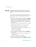
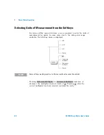
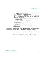
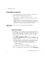
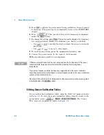
In various softkey menu structures, you are required to enter the units of 
measurement for power. In some cases, due to the wide power range 
available, the following menu is displayed:

Pressing 

 or 

 increases or 

decreases the multiplier shown in front of 

. Pressing 

 after the 

correct multiplier has been selected confirms the entry.

Increment


Decrement


Multiplier

Multiplier

Cancel

mW

Cancel

mW

nW

W

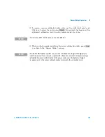
N O T E

Some softkeys may be grayed out so that an invalid value cannot be entered.

Increment Multiplier

Decrement Multiplier

W

W

Summary of Contents for E4418B

Page 1: ...Agilent Technologies Agilent E4418B Power Meter User s Guide ...

Page 2: ... in this document that conflict with these terms the warranty terms in the sep arate agreement shall control Technology Licenses The hardware and or software described in this document are furnished under a license and may be used or copied only in accordance with the terms of such license Restricted Rights Legend U S Government Restricted Rights Soft ware and technical data rights granted to the ...

Page 3: ... designated by Agilent Technologies Buyer shall prepay shipping charges to Agilent Technologies and Agilent Technologies shall pay shipping charges duties and taxes for products returned to Aglent Technologies from another country Agilent Technologies warrants that its software and firmware designated by Agilent Technologies for use with an instrument will execute its programming instructions when...

Page 4: ...es recommends a two years calibration cycle for the E4418B EPM Series power meter WARNING A warning calls attention to a procedure practice or the like which if not correctly performed or adhered to could result in injury or the loss of life Do not proceed beyond a warning until the indicated conditions are fully understood and met CAUTION A caution calls attention to a procedure practice or the l...

Page 5: ...ating switch for Stand by mode Note the instrument is NOT isolated from the mains when the switch is pressed To isolate the instrument the mains coupler mains input cord should be removed from the power supply This symbol indicates the operating switch for On mode External Protective Earth Terminal While this is a Class I product provided with a protective earthing conductor in a power cord an ext...

Page 6: ...only No operator serviceable parts inside Refer servicing to qualified personnel To prevent electrical shock do not remove covers For continued protection against fire hazard replace the line fuse s only with fuses of the same type and rating for example normal blow time delay etc The use of other fuses or material is prohibited WARNING Before this instrument is switched on make sure it has been p...

Page 7: ...rectives if accompanied by a year it signifies when the design was proven This ISM device complies with Canadian ICES 001 Cet appareil ISM est conforme à la norme NMB 001 du Canada This is the symbol of an Industrial Scientific and Medical Group 1 Class A product The CSA mark is a registered trademark of the Canadian Standards Association ...

Page 8: ...iance with IEC 60529 1989 Degrees of Protection Provided by Enclosures IP Code Level IPx4 is attained if and only if the carry case Agilent Technologies part number 34141A is fitted User Environment This product is designed for use in a sheltered environment avoiding extreme weather conditions in accordance with Pollution Degree 3 defined in IEC 60664 1 with the carry case Agilent Technologies par...

Page 9: ...5 T 19 Typprufung Manufacturers Declaration This statement is provided to comply with the requirements of the German Sound DIN 45635 T 19 Typprufung Sound Pressure LpA 70 dB At operator position Normal operation According to ISO 7779 Type Test Australian EMC Regulations The C Tick mark is a registered trademark of the Spectrum Management Agency of Australia This signifies compliance with the Austr...

Page 10: ...f Conformity DoC for this instrument is available on the Web site You can search the DoC by its product model or description http regulations corporate agilent com DoC search htm NOTE If you are unable to search for the respective DoC please contact your local Agilent representative ...

Page 11: ...th the above options except Option ABA For Option ABA the Programming Guide is available only by ordering Option 0BF Agilent Technologies E4418B E4419B Service Guide is available by ordering Option 915 Agilent Technologies E4418B E4419B CLIPs Component Location and Information Pack is available by ordering E4418 90031 Useful information on SCPI Standard Commands for Programmable Instruments can be...

Page 12: ...ment Option 909 provides rackmount kit for two instruments Option 915 provides the Agilent E4418B E4419B Service Guide Option 916 provides an additional Agilent E4418B User s Guide and Agilent E4418B E4419B Programming Guide Option 1BN provides MIL STD 45662A Certificate of Calibration Option 1BP provides MIL STD 45662A Certificate of Calibration and data Available Accessories Agilent 34161A acces...

Page 13: ...seful when you are operating the power meter from the front panel 3 Menu Reference Chapter 3 This chapter details diagrammatically the menu maps for the power meter It also gives a description of all the power meter s keys 4 Error Messages Chapter 4 This chapter lists the error messages that may appear as you are working with the power meter Each description contains information to help you diagno...

Page 14: ...xiv E4418B Power Meter User s Guide THIS PAGE HAS BEEN INTENTIONALLY LEFT BLANK ...

Page 15: ...on Instructions viii Regulatory Information ix List of Related Publications xi Agilent Technologies E4418B Options xii Available Accessories xii About this Guide xiii 1 Getting Started Introduction 2 Turning On the Power Meter 3 The Front Panel at a Glance 5 The Display Layout 8 Selecting Your Display Layout 11 Window Symbols 14 Warning Symbol 14 Confirmation Window 14 Wait Symbol 15 One of N Entr...

Page 16: ...ting Using TTL Inputs 35 Making Measurements with the Agilent E Series Power Sensors and N8480 Series Power Sensors excluding Option CFT 39 Procedure 39 Making Measurements with the Agilent 8480 Series Power Sensors and N8480 Series Power Sensors with Option CFT 41 Procedure 41 Making Measurements using Sensor Calibration Tables 44 Selecting a Sensor Calibration Table 45 Making the Measurement 45 ...

Page 17: ...80 RS232 RS422 81 Remote Interface Overview 83 Programming Language Selection 85 Recorder Output 86 Leveling a Source Output 87 Saving and Recalling Power Meter Configurations 88 How Measurements are Calculated 90 Presetting the Power Meter 91 Preset Conditions 91 Self Test 94 Power On Self Test 94 Front Panel Selection of Self Tests 95 Remote Testing 97 Test Descriptions 98 Operator Maintenance 1...

Page 18: ...tem Inputs Menu 3 of 4 117 System Inputs Menu 4 of 4 118 Zero Cal Menu 119 Front Panel Menu Reference 120 Diagrammatical keys 142 4 Error Messages Introduction 146 Error Messages 148 5 Specifications Introduction 156 Power Meter Specifications 157 Meter 157 Accuracy 158 1 mW Power Reference1 160 Power Meter Supplemental Characteristics 161 Measurement Speed 161 Zero Drift of Sensors 161 Measuremen...

Page 19: ...Characteristics 171 Rear Panel Connectors 171 Environmental Characteristics 172 General Conditions 172 Operating Environment 172 Storage Conditions 172 General 173 Dimensions 173 Weight 173 Safety 173 Remote Programming 174 Nonvolatile Memory 174 ...

Page 20: ...xx E4418B Power Meter User s Guide THIS PAGE HAS BEEN INTENTIONALLY LEFT BLANK ...

Page 21: ...ed Signal 68 Figure 2 11 Limits Checking Application 71 Figure 2 12 Limits Checking Results 71 Figure 2 13 Remote I O TTL Outputs 73 Figure 2 14 Pass Fail Limit Indicators 75 Figure 2 15 Digital Display 76 Figure 2 16 Analog Display 76 Figure 2 17 Digital and Analog Display 76 Figure 2 17 Digital and Analog Display 76 Figure 2 18 RS232 422 Pin Assignment 81 Figure 2 19 Interface Overview Examples ...

Page 22: ...xxii E4418B Power Meter User s Guide THIS PAGE HAS BEEN INTENTIONALLY LEFT BLANK ...

Page 23: ...puts Control Logic 35 Table 2 3 TTL Input Timing Diagram 1 36 Table 2 4 TTL Inputs Timing Diagram 2 37 Table 2 5 Measurement Units 59 Table 2 6 Range of Values for Window Limits 72 Table 3 1 Combination of Sensor Type and Correction Applied to Current Measurement 121 Table 5 1 Zero Set Specifications 158 Table 5 2 Noise Multiplier 162 Table 5 3 Power Sensor Specifications 162 Table 5 4 Settling Ti...

Page 24: ...xxiv E4418B Power Meter User s Guide THIS PAGE HAS BEEN INTENTIONALLY LEFT BLANK ...

Page 25: ...t Technologies 1 Getting Started Introduction 2 Turning On the Power Meter 3 The Front Panel at a Glance 5 The Display Layout 8 Window Symbols 14 The Rear Panel at a Glance 16 Adjusting the Carrying Handle 18 Rack Mounting the Power Meter 19 ...

Page 26: ...nt panel operations The front panel consists of both keys and softkeys which allow you to select various functions and operations When some keys are selected the corresponding softkey labels are displayed on the power meter display If you are using the power meter remotely refer to the Agilent Technologies E4418B 4419B Programming Guide for remote operating details NOTE The N8480 Series power sens...

Page 27: ...ful the error annunciator turns on If this occurs contact your Agilent Technologies Sales and Service office for instructions on returning the power meter to Agilent Technologies for service CAUTION This instrument is designed for use in Installation Category II and Pollution Degree 2 per IEC 1010 and 664 respectively CAUTION This instrument has an autoranging line voltage input be sure the supply...

Page 28: ...e end of the sensor cable to the power meter s channel input and the other end to the power sensor 4 Making a measurement A minimum warm up time of 30 minutes is recommended before accurate measurements can be made Prior to making your first measurement you must zero and calibrate the sensor and meter combination Refer to Chapter 2 for further information if you are not familiar with zeroing calib...

Page 29: ... remote mode that is GPIB RS232 or RS422 operation then pressing this key places the power meter in local mode provided local lock out LLO is not enabled 2 Keys relating to the display layout This key allows you to select the upper or lower measurement window on the power meter s display The window which is selected is highlighted by a shadowed box Any measurement setup you create is implemented i...

Page 30: ...rol of the power meter as a system The only other key which affects system parameters is the key Refer to Chapter 3 for further information about this key and its softkey menu 6 Dedicated Window keys with softkey menus These keys allow access to softkey menus which affect the setup of the measurement windows Refer to Chapter 3 for further information about these keys and their softkey menus 7 Dedi...

Page 31: ...ou to move through all pages of a menu The bottom right of the power meter display indicates the number of pages in the menu For example if 1 of 2 is displayed pressing moves you to 2 of 2 Pressing again moves you back to 1 of 2 This key allows you to move back one level in the softkey menu Repeatedly pressing accesses a menu which allows you to increase and decrease the display contrast 12 Softke...

Page 32: ...ation or LCL local front panel operation For GPIB operation the second field displays TLK if the power meter is addressed to talk or LSN if it is addressed to listen The third field indicates an SRQ service request For RS232 and RS422 operation the second field displays RX when data is being received The third field displays TX when the power meter is transmitting data The fourth field indicates E...

Page 33: ...its this field is empty If the measurement result is less than the minimum limit set Undr Lmt is displayed If the measurement result is more than the maximum limit set Over Lmt is displayed Refer to Setting Measurement Limits on page 70 for further information 10 This field displays Rel if relative mode is on Refer to Making Relative Measurements on page 61 for further information 11 This field di...

Page 34: ...xyHz nn a 5 xxx xyHz 6 xxx xyHz a Where y is the frequency multiplier M or G nn is the sensor calibration table number and a is the frequency dependent offset table letter Table 1 2 List of Possible Combinations for the Upper and Lower Display Lines Reference Number Sensor Series Sensor Correction Frequency Dependent Offset Correction 1 8480 Series sensors N8480 Series sensors with Option CFT Dire...

Page 35: ...ety of different measurements and windows depending on your needs The following diagram details the various options available to you Display Format Upper Window Lower Window Display One Window Two Windows Digital Display Analog Display Digital Display Analog Display Digital Display Analog Display Select using Select using Select using Select using Display Format ...

Page 36: ...ital display is the one which is highlighted by the dark box 2 Press The display remains the same apart from the fact that it is now the lower window which is an analog display that is highlighted by the dark box 3 Press The display now only shows the one window This is the analog window which in the previous step was selected with the key 4 Press Dgtl should be highlighted The display shows a dig...

Page 37: ...r User s Guide 13 6 Press The upper window is now the selected window and is highlighted by the black box 7 Press Anlg should be highlighted The upper window now displays an analog meter 8 Select the digital display using Meter Dgtl Anlg ...

Page 38: ... list you are required to enter an alphanumeric value Warning Symbol The warning symbol is displayed either directly in the measurement window or in a pop up window when such an event occurs A pop up window is displayed for approximately two seconds The text in the pop up window gives details of the warning type This symbol may also appear on a measurement window for example to indicate that a pow...

Page 39: ...ow It may appear for example during zeroing or calibration One of N Entry Window This pop up window is displayed when you are required to select an entry using and from the list Numeric or Alphanumeric Entry Window This pop up window is displayed when you are required to modify numeric or alphanumeric data The and keys move the position of the cursor The and keys increment and decrement the alphan...

Page 40: ...el input Refer to Recorder Output on page 86 for further information 4 Power socket This power meter has an auto configuring power supply This allows it to operate over a range of voltages without manually being set to a certain voltage 5 Fuse An F3 15AH fuse is installed for all voltage supplies 6 GPIB This connector allows the power meter to be controlled remotely using the General Purpose Inter...

Page 41: ...rial numbers on page 104 for further information 9 Rmt I O This connector is an RJ 45 series shielded modular jack assembly It provides a TTL logic level output when a measurement exceeds a predetermined limit TTL inputs are also provided to initiate zero and calibration cycles 10 Ground Connector Binding post accepts 4 mm plug or bare wire connection ...

Page 42: ...8 E4418B Power Meter User s Guide Adjusting the Carrying Handle To adjust the position grasp the handle by the sides and pull outward Rotate the handle to the desired position Bench top viewing positions Carrying position ...

Page 43: ...re included with each rack mounting kit Any Agilent System II instrument can be rack mounted besides the Agilent E4418B power meter To rack mount the power meter 1 Remove the handle by rotating it to the vertical position and pulling the ends outward 2 Remove the rubber bumper by stretching a corner and sliding it off To rack mount a single instrument order Option 908 or adapter kit 5063 9240 Fron...

Page 44: ...nt two instruments side by side order Option 909 or lock link kit 5061 9694 and flange kit 5063 9212 To install one or two instruments in a sliding support shelf order shelf 5063 9255 and slide kit 1494 0015 for a single instrument also order filler panel 5002 3999 ...

Page 45: ...alibration Tables 44 Making Measurements using Frequency Dependent Offset Tables 53 Setting the Units of Measurement 59 Selecting Units of Measurement from the Softkeys 60 Making Relative Measurements 61 Setting the Resolution 62 Setting Offsets 63 Setting Averaging 65 Measuring Pulsed Signals 68 Setting Measurement Limits 70 Selecting a Digital or Analog Display 76 Setting the Range 79 Configurin...

Page 46: ... with Option CFT on page 41 Making Measurements using Sensor Calibration Tables on page 44 Making Measurements using Frequency Dependent Offset Tables on page 53 Setting the Units of Measurement on page 59 Selecting Units of Measurement from the Softkeys on page 60 Making Relative Measurements on page 61 Setting the Resolution on page 62 Setting Offsets on page 63 Setting Averaging on page 65 Meas...

Page 47: ...Power Meter Operation 2 E4418B Power Meter User s Guide 23 Contacting Agilent Technologies on page 103 ...

Page 48: ...if AC power is lost while connected to an AC source a pop up window displays the message Running Under Battery Power When this screen is visible the backlight mode see Backlight on page 26 is over ridden and the backlight is on continuously Pressing the softkey returns the display to the previous screen Carry Case A soft carry or operating case is available which makes it easy to transport and ope...

Page 49: ...represented on an analog meter scale Below the analog scale is a message indicating the estimated power meter running time under battery operation with the present charge level Running time can be increased by operating the power meter with the display backlight turned off see Backlight on page 26 Figure 2 1 Battery Status When the power meter is running on battery power and there are less than 10...

Page 50: ... the power meter under battery power you can turn the display backlight off or on or set it to timed mode In timed mode the display backlight turns off 10 minutes after the last key press the display can be turned on again by pressing any key Working with the backlight off reduces the drain on the battery and increases the operating time available by approximately 50 The display can be comfortably...

Page 51: ...number E9287A this can only be used in power meters with Option 001 installed WARNING This product uses a Nickel Metal Hydride battery Do not short circuit the battery terminals Do not subject the battery to excessive heat Do not dispose of by burning Refer to your local country regulatory requirements on the disposal of Nickel Metal Hydride batteries CAUTION Observe static precautions while remov...

Page 52: ...pull the battery assembly clear of its slot in the power meter 3 Support the closure assembly on a flat surface 4 Pinch the release tab between finger and thumb while 5 lightly pressing down on the battery module 1 2 Release Tab Battery Module Closure Assembly 3 4 5 Replacing the battery is basically a reversal of the removal procedure Figure 2 2 Battery Removal Replacement ...

Page 53: ...is recommended when a 5 C change in temperature occurs when you change the power sensor every 24 hours prior to measuring low level signals For example 10 dB above the lowest specified power for your power sensor Zero Cal Lockout The Zero Cal Lockout facility provides a mean of ensuring that a measurement cannot be taken until the connected sensor has been zeroed and calibrated If the Zero Cal Loc...

Page 54: ... the wait symbol is displayed Offset relative and duty cycle settings are ignored during calibration Calibration Procedure Using Agilent E Series Power Sensors and N8480 Series Power Sensors excluding Option CFT The following procedure describes how you calibrate the power meter with an Agilent E Series power sensor or N8480 Series power sensor excluding Option CFT Since the power meter automatica...

Page 55: ...wer sensors with Option CFT Cal Cal NOTE V8486A and W8486A sensors For most 8480 Series sensors the correct A type or D type linearity correction table is automatically selected The linearity type field on the measurement screen is grayed out Under the gray out condition the selected linearity correction table that is displayed on the screen is irrelevant to the correct linearity correction table ...

Page 56: ...ue is not correct press The power meter displays the reference calibration factor in a pop up window Modify this reference calibration factor see below as desired Use or to modify the digit on which the cursor is currently positioned Use or to move to other digits 3 To confirm your choice press 4 Connect the power sensor to the POWER REF output 5 Press to calibrate the power meter During calibrati...

Page 57: ... a 75 Ω f to 50 Ω m N Type adapter 1250 0597 to connect to the reference calibrator Remove this adapter from the power sensor input before making measurements Agilent R8486A Agilent Q8486A Agilent V8486A Agilent W8486A Agilent R8486D Agilent Q8486D Agilent N8486AR Agilent N8486AQ The waveguide power sensors have two connectors The N Type connector is the one which is used to calibrate the power me...

Page 58: ...easurements Agilent 8487A Agilent N8487A Agilent N8488A This power sensor requires an APC 2 4 f to 50 Ω m N Type adapter 08487 60001 to connect to the power meter Remove this attenuator before making measurements Agilent 8487D Prior to the power meter being zeroed and calibrated an Agilent 11708A 30 dB reference attenuator and an APC 2 4 f to 50 Ω m N Type adapter 08487 60001 should be connected b...

Page 59: ...lded modular jack with the TTL input pins connected as shown in Figure 2 3 Figure 2 3 Rmt I O Port TTL Inputs The TTL inputs are active low and control the zero and calibration functions as shown in Table 2 2 Pin Number Connection 1 none 2 Ground 3 Upper Window TTL Output 4 Lower Window TTL Output 5 TTL Input 1 6 TTL Input 2 7 Ground 8 Ground 1 2 3 4 5 6 7 8 Table 2 2 TTL Inputs Control Logic Inpu...

Page 60: ...f input 300 ms T2 Time between input detection and start of zero cal cycle This is determined by the number of averages x sample rate or if there is an existing zero cal operation in progress the time for this current operation to complete Note that the worst case is 1024 averages x 50 ms 51 2 s For front panel operation in free run mode the time is 1 x 50 ms Max 50 ms typical Min 0 ms T3 Maximum ...

Page 61: ...FT Cal 6 s 8480 Series 7 s E Series 9 s N8480 Series exclude Option CFT 6 s N8480 Series with Option CFT All timings based on 100 ms firmware polling Table 2 4 TTL Inputs Timing Diagram 2 Timing of zero cal inputs for condition 00 Time Description Value T5 Maximum time between inputs going low 100 ms T6 Minimum overlap of low inputs 200 ms Table 2 3 TTL Input Timing Diagram 1 Inputs Operation T5 T...

Page 62: ...omplete Note that the worst case is 1024 averages x 50 ms 51 2 s For front panel operation in free run mode the time is 1 x 50 ms 4 s T8 Time for cal operation to complete Cal 6 s 8480 Series 7 s E Series 9 s N8480 Series exclude Option CFT 6 s N8480 Series with Option CFT All timings based on 100 ms firmware polling If both TTL inputs are simultaneously low under any circumstances other than thos...

Page 63: ...te the power meter 2 Set the frequency for the signal you want to measure 3 Take a reading Procedure The following procedure details how to make a measurement on channel A of the power meter 1 Ensure that no power is applied to the power sensor 2 Press 3 Press During zeroing which takes approximately 10 seconds the wait symbol is displayed 4 Connect the power sensor to the POWER REF output 5 Press...

Page 64: ...surement result is now displayed Example To make a measurement using an Agilent E Series power sensor The frequency of the signal to be measured is 100 MHz Disconnect the power sensor from any source Press Press Connect the power sensor to the POWER REF output Press Press Use the and keys to enter 100 Press Connect the power sensor to the signal to be measured The measurement result is now display...

Page 65: ...ke measurements without using sensor calibration tables that is inputting the individual calibration factor for a frequency prior to making the measurement This method is advantageous if you are only measuring at one frequency as entering all the calibration data in this instance is not required To make measurements without sensor calibration tables perform the following steps 1 Zero and calibrate...

Page 66: ...ss 7 Press to calibrate the power meter During calibration the wait symbol is displayed The power meter automatically turns on the POWER REF output 8 Press The current setting of the calibration factor is displayed under the softkey To change this setting press The power meter displays the calibration factor in a pop up window Modify this calibration factor see below as desired Use or to modify th...

Page 67: ...d a calibration factor of 97 8 at the measurement frequency Disconnect the power sensor from any source Press Press Press Use the and keys to enter 99 8 Press Connect the power sensor to the POWER REF output Press Press Use the and keys to enter 97 8 Press Connect the power sensor to the signal to be measured The measurement result is now displayed Zero Ref CF Cal Cal Fac ...

Page 68: ... calibration factors are used to correct measurement results Using sensor calibration tables provides you with a quick and convenient method for making power measurements over a range of frequencies using one or more power sensors The power meter is capable of storing 20 sensor calibration tables of 80 frequency points each To use sensor calibration tables you 1 Select the table to work on a chann...

Page 69: ...To make the power measurement you zero and calibrate the power meter then set it for the frequency of the signal you want to measure The power meter automatically selects the calibration factor from the sensor calibration table 1 Press 2 Press During zeroing which takes approximately 10 seconds the wait symbol is displayed 3 The setting of the reference calibration factor is obtained from the sens...

Page 70: ...t result is now displayed Editing Sensor Calibration Tables You can edit sensor calibration tables using the Edit Cal menu as shown in Figure 2 5 To view the sensor calibration tables currently stored in the power meter press The Sensor Tbls screen is displayed as shown in Figure 2 4 Cal Freq Freq NOTE If the measurement frequency does not correspond directly to a frequency in the sensor calibrati...

Page 71: ...2A2 HP 8483A HP 8481D HP 8485A HP R8486A HP Q8486A HP R8486D HP 8487A There are also ten sensor calibration tables named CUSTOM_0 through CUSTOM_9 which do not contain any data when the power meter is shipped from the factory 1 DEFAULT is a sensor calibration table in which the reference calibration factor and calibration factors are 100 This sensor calibration table can be used during the perform...

Page 72: ... rules apply to naming sensor calibration tables The name must consist of no more than 12 characters All characters must be upper or lower case alphabetic characters or numeric 0 9 or an underscore _ No other characters are allowed No spaces are allowed in the name 2 To edit the parameter you currently have selected press The power meter displays the data in a pop up window Modify this data see be...

Page 73: ...ensor calibration table press to return to the Sensor Tables screen Delete NOTE You can only edit the table name you cannot delete it Done NOTE Ensure that the frequency points you use cover the frequency range of the signals you want to measure If you measure a signal with a frequency outside the frequency range defined in the sensor calibration table the power meter uses the highest or lowest fr...

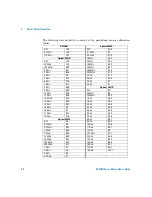
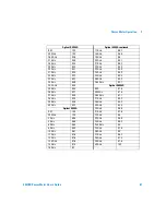
Page 74: ...7 2 GHz 96 4 6 GHz 97 4 3 GHz 93 7 GHz 97 1 4 GHz 91 8 GHz 96 6 Agilent 8481D 9 GHz 96 2 RCF 99 10 GHz 95 4 50 MHz 99 11 GHz 94 9 500 MHz 99 5 12 4 GHz 94 3 1 GHz 99 4 13 GHz 94 3 2 GHz 99 5 14 GHz 93 2 3 GHz 98 6 15 GHz 93 4 GHz 98 6 16 GHz 93 5 GHz 98 5 17 GHz 92 7 6 GHz 98 5 18 GHz 91 8 7 GHz 98 6 Agilent 8482A 8 GHz 98 7 RCF 98 9 GHz 99 5 0 1 MHz 98 10 GHz 98 6 0 3 MHz 99 5 11 GHz 98 7 1 MHz 9...

Page 75: ... 33 GHz 93 7 26 GHz 92 2 34 GHz 94 9 26 5 GHz 92 1 34 5 GHz 94 5 Agilent R8486D 35 GHz 94 4 RCF 97 6 36 GHz 93 7 50 MHz 97 6 37 GHz 94 9 26 5 GHz 97 1 38 GHz 93 5 27 GHz 95 3 39 GHz 93 9 28 GHz 94 2 40 GHz 92 3 29 GHz 94 5 Agilent 8485A 30 GHz 96 6 RCF 100 31 GHz 97 6 50 MHz 100 32 GHz 98 2 GHz 99 5 33 GHz 98 9 4 GHz 98 9 34 GHz 99 5 6 GHz 98 5 34 5 GHz 99 8 GHz 98 3 35 GHz 97 6 10 GHz 98 1 36 GHz...

Page 76: ...98 3 47 GHz 85 4 11 GHz 98 1 48 GHz 83 2 12 GHz 97 9 49 GHz 81 6 13 GHz 98 50 GHz 80 2 14 GHz 98 2 Agilent Q8486A 15 GHz 97 7 RCF 100 16 GHz 96 8 50 MHz 100 17 GHz 97 33 5 GHz 91 3 18 GHz 96 3 34 5 GHz 92 19 GHz 95 9 35 GHz 91 7 20 GHz 95 2 36 GHz 91 5 21 GHz 95 6 37 GHz 92 1 22 GHz 95 5 38 GHz 91 7 23 GHz 95 4 39 GHz 91 24 GHz 95 40 GHz 90 7 25 GHz 95 4 41 GHz 90 3 Agilent 8487A 42 GHz 89 5 26 GH...

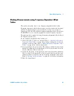
Page 77: ...e frequency dependent offset tables you 1 Select the table to work on a channel Refer to Selecting a Frequency Dependent Offset Table on page 54 for further information If you are required to edit the table refer to Editing Frequency Dependent Offset Tables on page 56 for further information 2 Zero and calibrate the power meter The reference calibration factor used during the calibration is automa...

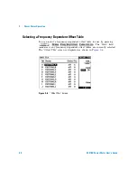
Page 78: ...fset Table You can select a frequency dependent offset table for use by pressing The State field indicates if any frequency dependent offset tables are currently selected The Offset Tbls screen is displayed as shown in Figure 2 6 Figure 2 6 Offset Tbls Screen Tables Freq Dep Offset Table Off On ...

Page 79: ... calibration table if selected and displayed under the softkey 4 Connect the power sensor to the POWER REF output 5 Press to calibrate the power meter During calibration the wait symbol is displayed The power meter automatically turns on the POWER REF output 6 Press The current setting of the frequency is displayed under the softkey 7 To change this setting press The power meter displays the frequ...

Page 80: ... directly to a frequency in the sensor calibration table if selected and the frequency dependent offset table being used the power meter calculates the calibration factor and offset using linear interpolation If you enter a frequency outside the frequency range defined in the sensor calibration table or the frequency dependent offset table the power meter uses the highest or lowest frequency point...

Page 81: ...n the range of 0 001 MHz to 999 999 GHz can be entered An offset in the range of 1 to 150 can be entered The following rules apply to naming frequency dependent offset tables The name must consist of no more than 12 characters All characters must be upper or lower case alphabetic characters or numeric 0 9 or an underscore _ No other characters are allowed No spaces are allowed in the name 2 To edi...

Page 82: ...edit the table name you cannot delete it Done NOTE Ensure that the frequency points you use cover the frequency range of the signals you want to measure If you measure a signal with a frequency outside the frequency range defined in the frequency dependent offset table the power meter uses the highest or lowest frequency point in the frequency dependent offset table to calculate the offset ...

Page 83: ... measurement modes Press then select the unit of measurement from or Softkeys which cannot be selected in your particular mode of operation appear with their text grayed out Table 2 5 Measurement Units dBm W dB NOTE When the unit of measurement is set to Watt it is possible that negative power measurements may be displayed when measuring low power levels Measurement Mode Relative Mode Off Relative...

Page 84: ... cases due to the wide power range available the following menu is displayed Pressing or increases or decreases the multiplier shown in front of Pressing after the correct multiplier has been selected confirms the entry Increment Decrement Multiplier Multiplier Cancel mW Cancel mW nW W NOTE Some softkeys may be grayed out so that an invalid value cannot be entered Increment Multiplier Decrement Mu...

Page 85: ... shown Relative mode is window dependent and when enabled displays Rel in the window to which it s applied Procedure To set a reference value on the currently selected window 1 Press 2 Press to use the current reading as the reference value This allows you to compare any measurement result in dB or percentage 3 is automatically set to On when is pressed Successive measurements are now displayed re...

Page 86: ...001 dB respectively if the measurement suffix is dBm or dB 1 2 3 or 4 significant digits respectively if the measurement suffix is W or The default value is 0 01 dB 3 digits To set the resolution on the currently selected window 1 Press The current setting of the resolution is highlighted on the softkey 2 To change this setting press until the required resolution setting is highlighted Resolution ...

Page 87: ...ve value compensates for a loss and a negative value compensates for a gain If either a channel or a display offset is set then Ofs is displayed To enter a channel offset which compensates for a loss or gain 1 Press 2 Press 3 Press The power meter displays the offset value in a pop up window Modify this offset see below as desired Use or to modify the digit on which the cursor is currently positio...

Page 88: ... 3 To confirm your choice press 4 is automatically set to On when a value is entered using Display offsets can be disabled and re enabled simply by pressing The display offset is a function of the window That is if you have selected a two window display each can have its own offset Figure 2 8 displays the effects of the channel and display offsets on the power meter s displayed reading Figure 2 8 ...

Page 89: ...ost power measurements The number of readings averaged together depends on the resolution and the power level currently being measured Figure 2 9 lists the number of readings averaged for each range and resolution when the power meter is in auto filter mode and is set to normal speed mode refer to the Agilent EPM 4418B 4419B Programming Guide for details of the readings averaged in the other speed...

Page 90: ...o access the filter menu 2 The current setting of averaging is displayed under the softkey To change this setting press A pop up window appears Use the or keys to set your filter length 3 To confirm your choice press The filter can be disabled and re enabled simply by pressing 10 dB 10 dB Minimum Sensor Power Maximum Sensor Power Power Sensor Dynamic Range 10 dB 10 dB 1 2 3 4 1 8 128 128 Resolutio...

Page 91: ...d power the filter can be set to re initialise upon detection of a step increase or decrease in the measured power Step detection can be set in both manual and automatic filter modes To set step detection 1 Press 2 Press the softkey to access the filter menu 3 Use the softkey to enable or disable step detection Input Settings Filter Step Det Off On ...

Page 92: ...The power meter measures the average power of the pulsed input signal and then divides the measurement result by the duty cycle value to obtain the pulse power reading The allowable range of values is 0 001 to 100 The default value is 1 000 If duty cycle is enabled then Dty Cyc is displayed An example of a pulsed signal is shown in Figure 2 10 Figure 2 10 Pulsed Signal NOTE Pulse measurements are ...

Page 93: ...ress 4 is automatically set to On when a value is entered using Duty cycle can be disabled and re enabled simply by pressing Input Settings Duty Cycle Duty Cycle Duty Cycle Off On Duty Cycle Duty Cycle Off On NOTE Pulse power averages out any aberrations in the pulse such as overshooting or ringing For this reason it is called pulse power and not peak power or peak pulse power In order to ensure a...

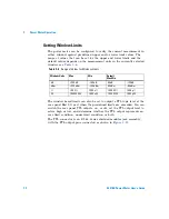
Page 94: ... measured against an upper and or lower limit value The range of values that can be set for upper and lower limits is 150 dBm to 230 dBm The default upper limit is 90 00 dBm and the default lower limit is 90 00 dBm To set the limits 1 Press The current setting of the maximum and minimum limits are displayed under the and softkeys respectively 2 To change either of these settings press the appropri...

Page 95: ...s In this application a swept frequency signal is applied to the input of the Device Under Test The power meter measures the output power The limits have been set at 4 dBm and 10 dBm A fail occurs each time the output power is outside these limits as shown in Figure 2 12 Power Meter Swept Source CHANNEL A INPUT OUT IN OUT Device Under Test 4 dBm 10 dBm Amplitude Frequency o o o o o o o Fail Fail ...

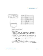
Page 96: ...put a TTL logic level at the rear panel Rmt I O port when the predefined limits are exceeded You can switch the rear panel TTL outputs on or off set the TTL output level to active high or low and determine whether the TTL output represents an over limit condition under limit condition or both The TTL connector is an RJ 45 Series shielded modular jack assembly with the TTL output pins connected as ...

Page 97: ...plays the current value in a pop up window Modify this value see below until the desired value is displayed Use or to modify the digit on which the cursor is currently positioned Use or to move to other digits 3 To confirm your choice press the appropriate measurement units Limits can be disabled and re enabled simply by pressing Pin Number Connection 1 none 2 Ground 3 Upper Window TTL Output 4 Lo...

Page 98: ...op up menu that appears 3 To select whether a high or low level TTL output represents a limits failure use the softkey to toggle between and TTL outputs can be disabled and re enabled simply by pressing Checking for Limit Failures Limit failures are displayed in the appropriate field in the measurement window on the power meter s display as shown in Figure 2 14 Limits TTL Output TTL Output Limits ...

Page 99: ...assed This is indicated by the limit field being empty This measurement has failed as the result is less than the minimum limit level set of 55 dBm This is indicated with the text Undr Lmt This measurement has failed as the result is more than the maximum limit level set of 60 dBm This is indicated with the text Over Lmt ...

Page 100: ...e Selecting a Digital or Analog Display The measurement windows can display the result in either a digital or analog format or both as shown in the following figures Figure 2 15 Digital Display Figure 2 16 Analog Display Figure 2 17 Digital and Analog Display ...

Page 101: ...priate softkey The power meter displays the current value in a pop up window Modify this value see below until the desired value is displayed Use or to modify the digit on which the cursor is currently positioned Use or to move to other digits 4 The choices available depend on the unit of measurement selected and the current measurement mode If the measurement unit selected is logarithmic then the...

Page 102: ...the measurement reading is outwith the minimum or maximum values set for the analog meter a warning message is displayed The analog meter also displays a digital reading This digital reading allows you to easily set the appropriate minimum and maximum values for the analog display Increment Multiplier Decrement Multiplier W W NOTE The analog display does not indicate as much measurement data as th...

Page 103: ...et either automatically or manually Use autoranging when you are not sure of the power level you will be measuring There are two manual settings either LOWER or UPPER The lower range is more sensitive than the higher range LOWER covers the range of 70 dBm to 13 5 dBm UPPER covers the range of 14 5 dBm to 20 dBm The default is AUTO To set the range 1 Press The current setting of the range is displa...

Page 104: ...e address is stored in nonvolatile memory and does not change when the power is switched off or after a remote interface reset Your GPIB bus controller has its own address Avoid using the bus controller s address for any instrument on the interface bus To set the GPIB address from the front panel 1 Press The current setting of the GPIB address is displayed under the softkey 2 To change this settin...

Page 105: ...e To select RS232 or RS422 as the remote interface press or RS232 422 Connector The serial port connector is a 9 pin male D type wired as shown in Figure 2 18 Figure 2 18 RS232 422 Pin Assignment Setting the RS232 422 Parameters This section explains how to set the baud rate word size parity number of stop bits pacing and echo for the serial interface Remote Interface Select Interface RS232 RS422 ...

Page 106: ...rom EVEN ODD ZERO ONE or NONE To confirm your choice press 6 Press to access page 2 of 2 This page allows you to set echo off and on and gives access to the pacing menu 7 Press to toggle between off and on When echo is on all received characters will be transmitted echoed back to the sender 8 Press to access the pacing menu which allows you to enable or disable various software and hardware pacing...

Page 107: ...p menu OFF Sets the DTR signal line permanently low ON Sets the DTR signal line permanently high IBFull Sets the DTR signal line high while the receiver buffer can accept more data and sets DTR low when the data buffer is full The transmitter is inhibited when DSR is low The softkey is greyed out if the RS422 interface is selected Remote Interface Overview You can view a summary of your remote int...

Page 108: ...2 Power Meter Operation 84 E4418B Power Meter User s Guide Figure 2 19 Interface Overview Examples Pressing the softkey returns the power meter display to the previous screen Done ...

Page 109: ...d Commands for Programmable Instruments You can determine the SCPI version with which the power meter is in compliance by sending the SYSTem VERSion command from the remote interface You cannot query the SCPI version from the front panel The language selection is stored in nonvolatile memory and does not change when power has been off or after a remote interface reset To select the interface langu...

Page 110: ... leveling or monitor the output power on a strip chart recorder A setup for recording swept measurements is shown in Figure 2 20 See Figure 2 22 for details on which power meter functions are implemented in the recorder output Figure 2 20 Test Setup for Recording Swept Measurements To access the Recorder menu press This menu allows you to switch the Recorder Output signal either on or off The and ...

Page 111: ...ed to determine the value which you should set for the Recorder Output maximum setting For example if you are measuring a power less than 1 mW and greater than 100 µW then set the recorder maximum value to 1 mW 3 To set the maximum value press and enter the appropriate value 4 Press and enter 0 W 5 Press to On 50 dBm 100 W 40 dBm 10 W 30 dBm 1 W 20 dBm 100 mW 10 dBm 10 mW 0 dBm 1 mW 10 dBm 100 µW ...

Page 112: ...nd keys to scroll through the displayed files When the required file is highlighted press 3 Press If you require to modify the name of a file 1 Press 2 Use the and keys to scroll through the displayed files When the required file is highlighted press The power meter displays the file name in a pop up window Modify this name see below until the desired name is displayed Use or to modify the charact...

Page 113: ...Power Meter Operation 2 E4418B Power Meter User s Guide 89 Figure 2 21 Save Recall Screen ...

Page 114: ...in which the various power meter functions are implemented in the measurement calculation Figure 2 22 How Measurements are Calculated Cal Factor Channel Functions Window Functions Averaging Channel Duty Offset Cycle Display Relative Offset Channel A Upper Window Limits Recorder Output Freq Dep Offset Window Limits Display Relative Offset Lower Window Window Limits ...

Page 115: ...ected is not affected Preset Conditions The number of windows displayed is two Measurement units used is set to dBm is set to 50 MHz is set to 100 is set to digital in the upper window and analog in the lower window is set to 20 000 dBm and 70 000 dBm is set to 3 is set to Off is set to 90 000 dBm and 90 000 dBm is set to Off is set to OVER is set to Low Freq Cal Fac Display Format Anlg Mtr Scalin...

Page 116: ...is set to 1 000 is set to Off is set to 0 000 dB is set to AUTO is set to 90 000 dbm and 90 000 dBm is set to Off is set to Off is set to 100 0 mW and 0 00 W is set to Off is not affected Rel Off On Offset Off On Offset Command Set Select Interface GPIB Addr Baud Rate Word Size Stop Bits Parity Pacing Echo Table Off On Filter Off On Filter Duty Cycle Off On Duty Cycle Offset Off On Offset Range Li...

Page 117: ...Power Meter Operation 2 E4418B Power Meter User s Guide 93 is set to On is set to 100 is not affected is set to Off Backlight Off On Ref CF Must Cal Off On TTL Inputs Off On ...

Page 118: ...er on self test is performed automatically when the power meter is turned on and takes approximately 10 seconds to complete The power on self test consists of the following tests RAM Battery Calibrator Measurement AssemblyFan Serial Interface Option 001 Battery Refer to Test Descriptions on page 98 if you require a description of each individual test As the power on self test takes place the messa...

Page 119: ...ists of the following tests Display Assembly Display RAM Bitmap Displays Serial Interface which accesses a menu which consists of the following tests UART Configuration Local Loop Back RS232 Loop Back RS422 Loop Back Each of these tests can be run individually Information on the instrument self test and confidence check are described on page 96 Refer to Test Descriptions on page 98 if you require ...

Page 120: ...r Measurement AssemblyFan Serial Interface As each test takes place the name of the test is listed on the screen While a test is running the message Testing appears next to the name of the test As each stage of the test is completed the message Testing is replaced by either the message Passed or Failed Confidence Check The confidence check requires you to carry out the following procedure Instruct...

Page 121: ...self test consists of the following tests ROM checksum RAM RAM Battery Display Assembly Calibrator Measurement Assembly Communications Assembly Implicit The communications assembly is tested implicitly in that the command will not be accepted or return a result unless the GPIB interface is functioning correctly Refer to Test Descriptions on page 98 if you require a description of each individual t...

Page 122: ...the checksum of the firmware and checks it against the pre defined checksum stored on the ROM A pass or a fail result is returned RAM This test carries out a read and write test on the instrument RAM RAM Battery When the firmware is first downloaded a known value is written into a battery backed memory location This test verifies that the value is still resident It returns a pass if the value is s...

Page 123: ...city of the Option 001 battery has not decayed below 70 of its original value The test is only performed on power meters fitted with Option 001 Calibrator The reference calibrator is turned on indicated by the POWER REF LED and measured internally A pass or fail result is returned Keyboard Front Panel only The power meter enters a mode where you are invited to press any key When a key is pressed i...

Page 124: ...plexer and digital signal processor If the expected voltages are measured a pass is recorded otherwise a fail is recorded The three circuits which are tested are the LCD contrast control the LED brightness control and the display temperature sensing diode Bitmap Display Front Panel only A series of bitmaps are displayed on the power meter showing two checkboards vertical lines horizontal lines obl...

Page 125: ...l For all voltages the power meter uses a 250 V F3 15AH 20 mm fast blow fuse with high breaking capacity Agilent part number 2110 0957 Replacing the Power Line Fuse 1 Remove the power cord from the power meter 2 Slide the fuse holder assembly from the rear panel as shown in Figure 2 23 3 Install the correct fuse in the In line position as shown in Figure 2 23 A spare fuse can be stored in the fuse...

Page 126: ...2 Power Meter Operation 102 E4418B Power Meter User s Guide Figure 2 23 Replacing the fuse In line fuse Spare fuse ...

Page 127: ...ing Your Power Meter for Service on page 107 Before calling Agilent Technologies Before calling Agilent Technologies or returning the power meter for service please make the checks listed in Check the Basics on page 104 If you still have a problem please read the warranty printed at the front of this guide If your power meter is covered by a separate maintenance agreement please be familiar with t...

Page 128: ...g used when the problem occurred Check that the test being performed and the expected results are within the specifications and capabilities of the power meter Check the power meter display for error messages Refer to Chapter 4 for further information Check operation by performing the self tests Check with a different power sensor Instrument serial numbers Agilent Technologies makes frequent impro...

Page 129: ...st four numbers The prefix letters indicate the country of manufacture This code is based on the ISO international country code standard and is used to designate the specific country of manufacture for the individual product The same product number could be manufactured in two different countries In this case the individual product serial numbers would reflect different country of manufacture code...

Page 130: ...n also contact one of the following centers and ask for a test and measurement sales representative United States tel 800 829 4444 fax 800 829 4433 Canada tel 877 894 4414 fax 800 746 4866 China tel 800 810 0189 fax 800 820 2816 Europe tel 31 20 547 2111 Japan tel 81 426 56 7832 fax 81 426 56 7840 Korea tel 080 769 0800 fax 080 769 0900 Latin America tel 305 269 7500 Taiwan tel 0800 047 866 fax 08...

Page 131: ...mation on the performance of the power meter 2 Use the original packaging materials or a strong shipping container that is made of double walled corrugated cardboard with 159 kg 350 lb bursting strength The carton must be both large enough and strong enough to accommodate the power meter and allow at least three to four inches on all sides of the power meter for packing material 3 Surround the pow...

Page 132: ...ap the power meter several times in the material to both protect the power meter and prevent it from moving in the carton 4 Seal the shipping container securely with strong nylon adhesive tape 5 Mark the shipping container FRAGILE HANDLE WITH CARE to ensure careful handling 6 Retain copies of all shipping papers ...

Page 133: ...109 E4418B Power Meter User s Guide Agilent Technologies 3 Menu Reference Introduction 110 The Front Panel Menu Maps 111 Front Panel Menu Reference 120 ...

Page 134: ...e Introduction This chapter is a reference to the softkey menu structure of the power meter The Front Panel Menu Maps starting on page 111 details the menus diagrammatically Front Panel Menu Reference starting on page 120 details the menus descriptively ...

Page 135: ...er some softkey labels have numeric values displayed under them These values show the current setting of that softkey Since these values are variable they are shown in a grayed out text on the following menu maps dBm W dB NOTE Depending on the power meter s setup you will be unable to select certain softkeys The text on these softkey labels appears grayed out Refer to the appropriate softkey descr...

Page 136: ...quency Cal Fac Menu Freq Cal Fac 50 00MHz 100 0 NOTE Depending on the power meter s setup you will be unable to select certain softkeys The text on these softkey labels appears grayed out Refer to the appropriate softkey descriptions for further information ...

Page 137: ...er User s Guide 113 Meas Setup Menu Meter Dgtl Anlg Anlg Mtr Scaling Limits Resolution 1 2 3 4 Display Format Off On Max 90 000 dBm Min 90 000 dBm TTL Output Max 20 000 dBm Min 70 000 dBm Off On Limits OVER Fail O P High Low TTL Output ...

Page 138: ...Offset 0 000dB Off On Off On Save Recall Done Enter Insert Edit Cancel Name Char Delete Char NOTE Depending on the power meter s setup you will be unable to select certain softkeys The text on these softkey labels appears grayed out Refer to the appropriate softkey descriptions for further information ...

Page 139: ...ble Edit Tables Offset Limits Length MAN AUTO Filter Off On Mode 128 Step Det Duty Cycle Duty Cycle 1 000 Filter See page 117 Remote Interface Range AUTO Agilent E Series sensors and N8480 Series sensors excluding Option CFT only Off On Off On Off On Off On NOTE Depending on the power meter s setup you will be unable to select certain softkeys The text on these softkey labels appears grayed out Re...

Page 140: ...dual Self Test Check Set Contrast Set Brightness Fan Keyboard Display Display Display Bitmap Assy RAM Displays Display Lithium Memory Measure Battery Calibrator Assembly Self Test Serial Diagnostic Battery Output Max Power Off On 100 0 mW Min Power 0 000 W Must Cal Off On Serial Interface UART Local RS232 Config Loop Back Loop Back See page 118 See page 118 RS422 Loop Back ...

Page 141: ... HP437B Remote Interface Cmd Set Select Configure Interface Interface Interface Overview RS422 RS232 GPIB Serial GPIB GPIB Addr 13 Pacing Parity NONE Word Size 8 Baud Rate 9600 Stop Bits 1 Echo On Off Tx Pacing Rx Pacing RTS CTS OFF DTR DSR OFF None Xon None Xon See page 115 IEEE 488 ...

Page 142: ...r User s Guide System Inputs Menu 4 of 4 Recorder Output Service Error List Display Version Self Test Serial Diagnostic Battery Backlight On Status Reset Tx Break Done Off Backlight Timed See page 116 See page 116 Backlight Must Cal Off On ...

Page 143: ...100 0 Cal Zero Power Ref Off On Must Cal Off On TTL Inputs Off On NOTE Depending on the power meter s setup you will be unable to select certain softkeys The text on these softkey labels appears grayed out Refer to the appropriate softkey descriptions for further information ...

Page 144: ...elect the upper or lower measurement window on the power meter s display The window which is selected is highlighted by a shadowed box and the set up you create is implemented in this window Press this key to access the dBm Watts menu which allows you to select the measurement units These can either be logarithmic dBm or dB or linear Watt or The default is logarithmic The text on some softkeys may...

Page 145: ...wer sensors Frequency can be entered Default value is 50 MHz The Cal Factor is obtained from the sensor calibration table but can be overridden by this softkey Frequency can be entered if a frequency dependent offset table is selected The Cal Factor can be entered Default value is 100 Agilent E Series power sensors Not Applicable Not Applicable Frequency can be entered Default value is 50 MHz The ...

Page 146: ...g this softkey is only possible when you are using an Agilent 8480 Series power sensor or N8480 Series power sensor with Option CFT The softkey menu structured to this key affects the currently selected window Press to select the upper or lower measurement window on the power meter s display The window which is selected is highlighted by a shadowed box and the set up you create is implemented in t...

Page 147: ...he measurement suffix is W or The default value is 3 that is 0 01 dB or 3 digits Press this softkey to access a menu where you can enter upper and lower limits for each display window which when exceeded will output a TTL logic level if enabled at the rear panel TTL outputs Refer to Setting Window Limits on page 72 for further information Press this softkey to toggle between the test limits being ...

Page 148: ...he TTL output level to active high or low Determine whether the TTL output represents an over limit condition under limit condition or both Press this softkey to toggle between switching the TTL output off and on Press this softkey to select whether the TTL output reflects an overlimit condition under limit condition or both Press this softkey to select whether a high or low level TTL output repre...

Page 149: ... Pressing this key numerous times eventually returns you to the Contrast menu which allows you to increase or decrease the display contrast Press this softkey to increase the display contrast Press this softkey to decrease the display contrast The softkey menu structured to this key affects the currently selected window Press this key to access the Rel Offset menu which allows you to compare any m...

Page 150: ...eter to the highlighted file First use the and keys to scroll through the displayed files When the required file is highlighted press Press this softkey to recall a required power meter setup from the highlighted file First use the and keys to scroll through the displayed files When the required file is highlighted press Press this softkey to change a file name First use the and keys to scroll bet...

Page 151: ...Inputs menu This menu allows you to set up a variety of conditions for your power meter for example GPIB address serial interface parameters sensor calibration tables averaging duty cycle range offset service It also allows you to review errors Press this softkey to access a menu which allows you to select and configure the remote interface select the command set you want to use or obtain an inter...

Page 152: ...ation using the RS422 Standard Press this softkey to access a menu which allows you to either configure the GPIB interface or the serial interface RS232 RS422 Press this softkey to access a menu which allows you to set the GPIB address Press this softkey to set the GPIB address of your power meter between 0 and 30 The default value is 13 A pop up window appears on the screen Use the and keys to ch...

Page 153: ...pe for the serial interface A pop up window appears on the screen allowing you to select from ODD EVEN ZERO ONE or NONE Press this softkey to access a menu which allows you to enable or disable various hardware and software pacing options Press this softkey to toggle between enabling and disabling the Xon Xoff transmitter software handshake When enabled Xon is highlighted otherwise None is highlig...

Page 154: ...n Echo is enabled received characters are transmitted back to the sender Press this softkey to access a menu which allows you to select between sensor calibration tables and frequency dependent offset tables Press this softkey to access a menu and screen which allows you to select and edit sensor calibration tables Use the and keys to scroll through the displayed sensor calibration tables Sensor c...

Page 155: ...m the first level of the System Inputs menu are displayed Press this softkey to access a menu and screen which allows you to select and edit frequency dependent offset tables Use the and keys to scroll through the displayed frequency dependent offset tables Press this softkey to access a menu and screen which allows you to modify add and remove frequency calibration factors and offsets from the cu...

Page 156: ...ent screen The softkeys from the first level of the System Inputs menu are displayed Press this softkey to select the type of linearity correction that will be applied to the sensor being used For most 8480 series sensors the correct A type or D type linearity correction table is automatically selected However for the V8486A and W8486A sensors the automatic selection must be overridden and the D t...

Page 157: ... to Setting the Range on page 79 for further information Press this softkey to access a menu which allows you to enter the upper and lower measurement limits Refer to Setting Measurement Limits on page 70 for further information Press this softkey to toggle between the test limits being on or off The default is Off Press this softkey to enter the upper measurement limit in the range 150 dBm to 230...

Page 158: ... is set using Press this softkey to toggle between the automatic AUTO and manual MAN filter modes In manual mode you enter the number of measurements to be averaged In automatic mode the number of measurements averaged is based on the measured power and uses a pre defined look up table Refer to Setting Averaging on page 65 for further information Press this softkey to enter the filter length The f...

Page 159: ... time is selected Press this softkey to return to the System Inputs menu Press this softkey to access a menu which allows you to modify the setup of the recorder output Refer to Recorder Output on page 86 for further information Press this softkey to switch the rear panel Recorder Output on or off The Recorder Output produces a DC voltage that corresponds to the selected input channel power level ...

Page 160: ... accurate measurement of its 1 mW POWER REF output Press this softkey to access a menu which allows you to select individual self tests to be run Press this softkey to perform a ROM Checksum verification test verify the memory and that the correct amount of RAM is present Press this softkey to verify that the firmware checksum is still resident in a battery backed memory location Press this softke...

Page 161: ... softkey to access a menu which gives you a selection of serial interface tests to perform Press this softkey to initiate a test which writes to the scratch register and reads back The test also sets the baud rate word length stop bits and parity then reads back from the UART to check that the settings are correct Press this softkey to initiate a UART local loop back diagnostic with the transmitte...

Page 162: ...d A softkey menu offers the following choices Run Test performs the RS422 loop back test and reports the results Cancel Test quit test and return to previous menu Press this softkey to access a menu which allows you to set the defaults for contrast and brightness Press this softkey to increase the display contrast Press this softkey to decrease the display contrast Press this softkey to set the de...

Page 163: ...e interface configuration This softkey is only present on power meters fitted with the battery Option 001 It is greyed out when the battery is not installed Press this softkey to produce a screen which shows How much charge the battery is holding The approximate running time left under battery power Either Using AC power if the battery is fully charged Charging battery or Using battery power as ap...

Page 164: ... Cal menu which allows you to zero and calibrate the power meter Refer to Calibrating the Power Meter on page 30 for further information Press this softkey to adjust channel A for a zero power reading with no power applied to the power sensor Refer to Zeroing and Calibrating the Power Meter on page 29 for further information Press this softkey to calibrate channel A with the connected power sensor...

Page 165: ...al Lockout facility On or Off When Zero Cal Lockout is On the power meter is prevented from making a measurement until the sensor connected has been zeroed and calibrated This softkey is coupled to the equivalent softkey in the System Inputs menu Press this softkey to disable or enable Off On the ZERO and CAL rear panel TTL inputs Power Ref Off On NOTE During calibration the power meter automatica...

Page 166: ...g alphanumeric data that is to be entered into the power meter This key moves the position of the cursor to the right on the currently selected parameter select fields for editing on the Edit Table screen Press this key to decrement the alphanumeric digit on which the cursor is currently positioned That is digits scroll 9 through 0 and characters lowercase z through a uppercase Z through A then un...

Page 167: ... Save and Recall screens Press this key to select the upper or lower measurement window on the power meter s display The window which is selected is highlighted by a shadowed box Any measurement setup you create using and is implemented in the selected window Press this key to choose from a one or a two window display Press this key to switch the power meter between on and standby When the power m...

Page 168: ...3 Menu Reference 144 E4418B Power Meter User s Guide THIS PAGE HAS BEEN INTENTIONALLY LEFT BLANK ...

Page 169: ...145 E4418B Power Meter User s Guide Agilent Technologies 4 Error Messages Introduction 146 Error Messages 148 ...

Page 170: ...he display In addition the errors are also written to the error queue If there are any errors in the error queue the front panel error annunciator is displayed as shown in Figure 4 1 Other errors can also be generated when the power meter is being operated over the remote interface These errors also display the error annunciator and are written to the error queue Figure 4 1 Error Annunciator Posit...

Page 171: ...discarded Once the errors are read they are removed from the error queue This opens a position at the end of the queue for a new error message if one is subsequently detected When all errors have been read from the queue further error queries return 0 No errors To delete all the errors in the queue from the front panel press then To delete all the errors in the queue remotely use the CLS clear sta...

Page 172: ... expected for the command You may have entered an extra parameter or added a parameter to a command that does not accept a parameter For example CAL 10 109 Missing parameter Fewer parameters were received than expected for the command You omitted one or more parameters that are required for this command For example AVER COUN 112 Program mnemonic too long A command header was received which contain...

Page 173: ... INIT CONT 0Hz 148 Character data not allowed A discrete parameter was received but a character string or a numeric parameter was expected Check the list of parameters to verify that you have used a valid parameter type For example MEM CLE CUSTOM_1 151 Invalid string data An invalid string was received Check to see if you have enclosed the character string in single or double quotes For example ME...

Page 174: ...ABLe FREQuency command are not in ascending order 221 Settings conflict This command occurs under a variety of conflicting conditions The following list gives a few examples of where this error may occur If the READ parameters do not match the current settings If you are in fast mode and attempting to switch on for example averaging duty cycle or limits Trying to clear a sensor calibration table w...

Page 175: ...onnected to channel A has not been calibrated then any command which would normally return a measurement result for example FETC READ or MEAS will generate this error message 231 Data questionable CAL ERROR Power meter calibration failed The most likely cause is attempting to calibrate without applying a 1 mW power to the power sensor 231 Data questionable Input Overload The power input to Channel...

Page 176: ...xample Linearity Temp Comp temperature compensation This indicates a failure with your Agilent E Series or N8480 Series power sensor Refer to your power sensor manual for details on returning it for repair 310 System error Option 001 Battery charger fault The power meter is connected to an AC power source the battery is not fully charged and it is not charging 310 System error Sensors connected to...

Page 177: ... require a description of this test 330 Self test Failed Serial Interface Fault Refer to Serial Interface on page 99 if you require a description of this test 350 Queue overflow The error queue is full and another error has occurred which could not be recorded 361 Parity error in program The serial port receiver has detected a parity error and consequently data integrity cannot be guaranteed 362 F...

Page 178: ...ample you may have executed a CONFigure command which does not generate data and then attempted to read data from the remote interface 430 Query DEADLOCKED A command was received which generates too much data to fit in the output buffer and the input buffer is also full Command execution continues but data is lost 440 Query UNTERMINATED after indefinite response The IDN command must be the last qu...

Page 179: ...echnologies 5 Specifications Introduction 156 Power Meter Specifications 157 Power Meter Supplemental Characteristics 161 Battery Option 001 Operational Characteristics 170 General Characteristics 171 Environmental Characteristics 172 General 173 ...

Page 180: ...range unless otherwise stated and after performing a zero and calibration Supplemental characteristics which are shown in italics are intended to provide information useful in applying the power meter by giving typical but nonwarranted performance parameters These characteristics are shown in italics or denoted as typical nominal or approximate For information on measurement uncertainty calculatio...

Page 181: ...ower sensors Single Sensor Dynamic Range 90 dB maximum Agilent E Series power sensors 50 dB maximum Agilent 8480 Series power sensors 55 dB maximum Agilent N8480 Series power sensors excluding Option CFT 50 dB maximum Agilent N8480 Series power sensors with Option CFT Display Units Absolute Watts or dBm Relative Percent or dB Display Resolution Selectable resolution of 1 0 0 1 0 01 and 0 001 dB in...

Page 182: ...dependent refer to Table 5 1 For Agilent E Series 8480 Series and N8480 Series power sensors this specification applies when zeroing is performed with the sensor input disconnected from the POWER REF Table 5 1 Zero Set Specifications Power Sensor Zero Set Agilent 8481A1 50 nW Agilent 8481B1 50 mW Agilent 8481D1 20 pW Agilent 8481H1 5 mW Agilent 8482A1 50 nW Agilent 8482B1 50 mW Agilent 8482H1 5 mW...

Page 183: ...on CFT 1 2 5 µW Agilent N8485A exclude Option CFT 1 25 nW Agilent N8486AR exclude Option CFT 1 25 nW Agilent N8486AQ exclude Option CFT 1 25 nW Agilent N8487A exclude Option CFT 1 25 nW Agilent N8488A exclude Option CFT 1 25 nW Agilent N8481A with Option CFT1 63 nW Agilent N8481B with Option CFT1 63 µW Agilent N8481H with Option CFT1 6 3 µW Agilent N8482A with Option CFT1 63 nW Agilent N8482B with...

Page 184: ...l metrology institutes of member states of the Metre Convention such as the National Institute of Standards and Technology in the USA are signatories to the Comité International des Poids et Mesures Mutual Recognition Arrangement Further information is available from the Bureau International des Poids et Mesures at http www bipm fr 2 This SWR specification is only warranted for the E4418B and the ...

Page 185: ...modes are available as shown along with the typical maximum measurement speed for each mode Normal 20 readings second x2 40 readings second Fast 200 readings second for Agilent E Series power sensors only Maximum measurement speed is obtained using binary output in free run trigger mode Zero Drift of Sensors Power sensor dependent refer to Table 5 3 ...

Page 186: ...1D power sensor in normal mode with the number of averages set to 4 the measurement noise is equal to 45 pW x 2 75 124 pW Table 5 2 Noise Multiplier Table 5 3 Power Sensor Specifications Number of Averages 1 2 4 8 16 32 64 128 256 512 1024 Noise Multiplier Normal Mode 5 5 3 89 2 75 1 94 1 0 0 85 0 61 0 49 0 34 0 24 0 17 Noise Multiplier x2 mode 6 5 4 6 3 25 2 3 1 63 1 0 0 72 0 57 0 41 0 29 0 2 Pow...

Page 187: ... pW Agilent E9300B 150 nW 700 nW Agilent E9301B 150 nW 700 nW Agilent E9300H 1 5 nW 7 nW Agilent E9301H 1 5 nW 7 nW Agilent N8481A exclude Option CFT 3 3 nW 80 nW Agilent N8481B exclude Option CFT 3 3 µW 80 µW Agilent N8481H exclude Option CFT 3 0 3 µW 8 µW Agilent N8482A exclude Option CFT 3 3 nW 80 nW Agilent N8482B exclude Option CFT 3 3 µW 80 µW Agilent N8482H exclude Option CFT 3 0 3 µW 8 µW ...

Page 188: ...lent N8486AR with Option CFT3 7 nW 114 nW Agilent N8486AQ with Option CFT3 7 nW 114 nW Agilent N8487A with Option CFT3 7 nW 114 nW 1 Within one hour after zero set at a constant temperature after a 24 hour warm up of the power me ter 2 The number of averages at 16 for normal mode and 32 for x2 mode at a constant temperature measured over a one minute interval and two standard deviations For Agilen...

Page 189: ... x2 speed modes Number of Averages 1 2 4 8 16 32 64 128 256 512 1024 Settling Time s Normal Mode 0 15 0 2 0 3 0 5 1 1 1 9 3 4 6 6 13 27 57 Response Time s x2 mode 0 15 0 18 0 22 0 35 0 55 1 1 1 9 3 5 6 9 14 5 33 10 dB 10 dB 10 dB 20 dB Minimum dBm Power 150 ms 6 6 s 500 ms 200 ms Settling Times Sensor Dynamic Range Maximum dBm 10 dB 10 dB 10 dB 20 dB Power 150 ms 3 5 s 350 ms 180 ms Settling Times...

Page 190: ...e power sensor s auto range switch point add 25 ms Refer to the relevant power sensor manual for further information For Agilent E Series power sensors in normal and x2 speed modes manual filter 10 dB decreasing power step Table 5 5 Settling Time Number of Averages 1 2 4 8 16 32 64 128 256 512 1024 Settling Time s Normal Mode 0 07 0 12 0 21 0 4 1 1 8 3 3 6 5 13 27 57 Response Time s x2 mode 0 04 0...

Page 191: ...power step normal and x2 speed modes 10 dB 10 dB 10 dB 60 dB Maximum dBm Minimum dBm Power Sensor 40 ms 3 4 s 210 ms 70 ms Settling Times Typical Dynamic Range 10 dB 10 dB 10 dB 60 dB Maximum dBm Minimum dBm Power Sensor 70 ms 6 5 s 400 ms 120 ms Settling Times Typical Dynamic Range Normal Mode x2 Mode ...

Page 192: ... 2 4 8 16 32 64 128 256 512 1024 Settling Time s Normal Mode 0 15 0 2 0 3 0 5 1 1 1 9 3 4 6 6 13 27 57 Response Time s x2 mode 0 15 0 18 0 22 0 35 0 55 1 1 1 9 3 5 6 9 14 5 33 10 dB 10 dB 10 dB 20 dB Minimum dBm Power 150 ms 6 6 s 1 s 200 ms Settling Times Sensor Dynamic Range Maximum dBm Normal Mode Typical 13 5 s 5 dB 10 dB 10 dB 10 dB 20 dB Power 150 ms 3 6 s 400 ms 180 ms Settling Times Sensor...

Page 193: ...cting for residual offsets Zero Drift This parameter is also called long term stability and is the change in the power meter indication over a long time usually one hour for a constant input power at a constant temperature after a defined warm up interval Measurement Noise This parameter is also known as short term stability and is specified as the change in the power meter indication over a short...

Page 194: ...ed by the product warranty Typical Operating Time Up to three hours with LED backlight on up to five hours with LED backlight off Charge Time Less than two hours to charge fully from an empty state 50 minutes charging enables one hour of operation with LED backlight ON 35 minutes charging enables one hour of operation with the LED backlight OFF Power meter is operational while it is charging Servi...

Page 195: ...bminiature connector Remote Input Output A TTL logic level is output when the measurement exceeds a predetermined limit TTL inputs are provided to initiate zero and calibration cycles RJ 45 series shielded modular jack assembly TTL output high 4 8 V max low 0 2 V max TTL input high 3 5 V min 5 V max low 1 V max 0 3 V min Ground Binding post accepts 4 mm plug or bare wire connection Line Power Inpu...

Page 196: ...2 and Radiated Interference Standard EN 55011 1991 CISPR11 1990 Group 1 Class A Operating Environment Temperature 0 ºC to 55 ºC Maximum Humidity 95 at 40 ºC non condensing Minimum Humidity 15 at 40 ºC non condensing Maximum Altitude 3000 meters 9840 feet Storage Conditions Storage Temperature 20 ºC to 70 ºC Non Operating Maximum Humidity 90 at 65 ºC non condensing Non Operating Maximum Altitude 15...

Page 197: ... W x 88 5 mm H x 348 3 mm D 8 5 in x 3 5 in x 13 7 in Weight Net 4 0 Kg 8 8 lb 5 0 Kg 11 lb with Option 001 Shipping 7 9 Kg 17 4 lb 8 9 Kg 19 6 lb with Option 001 Safety Conforms to the following Product Specifications EN61010 1 1993 IEC 1010 1 1990 A1 CSA C22 2 No 1010 1 1993 EN60825 1 1994 IEC 825 1 1993 Class 1 Low Voltage Directive 72 23 EEC ...

Page 198: ... to IEEE 488 2 RS 232 and RS 422 interfaces are supplied as standard Command Language SCPI standard interface commands Agilent 437B code compatible GPIB Compatibility SH1 AH1 T6 TE0 L4 LE0 SR1 RL1 PP1 DC1 DT1 C0 Nonvolatile Memory Battery Lithium Polycarbon Monoflouride approximate lifetime 5 years at 25 C ...

Page 199: ...ax 800 746 4866 China tel 800 810 0189 fax 800 820 2816 Europe tel 31 20 547 2111 Japan tel 81 426 56 7832 fax 81 426 56 7840 Korea tel 080 769 0800 fax 080 769 0900 Latin America tel 305 269 7500 Taiwan tel 0800 047 866 fax 0800 286 331 Other Asia Pacific Countries tel 65 6375 8100 fax 65 6755 0042 Or visit Agilent World Wide Web at www agilent com find assist Product specifications and descripti...

Reviews: