background image

6

User’s and Service Guide 

E4438C Option SP2

Technical Specification

Technical Specification

Startup

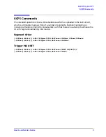
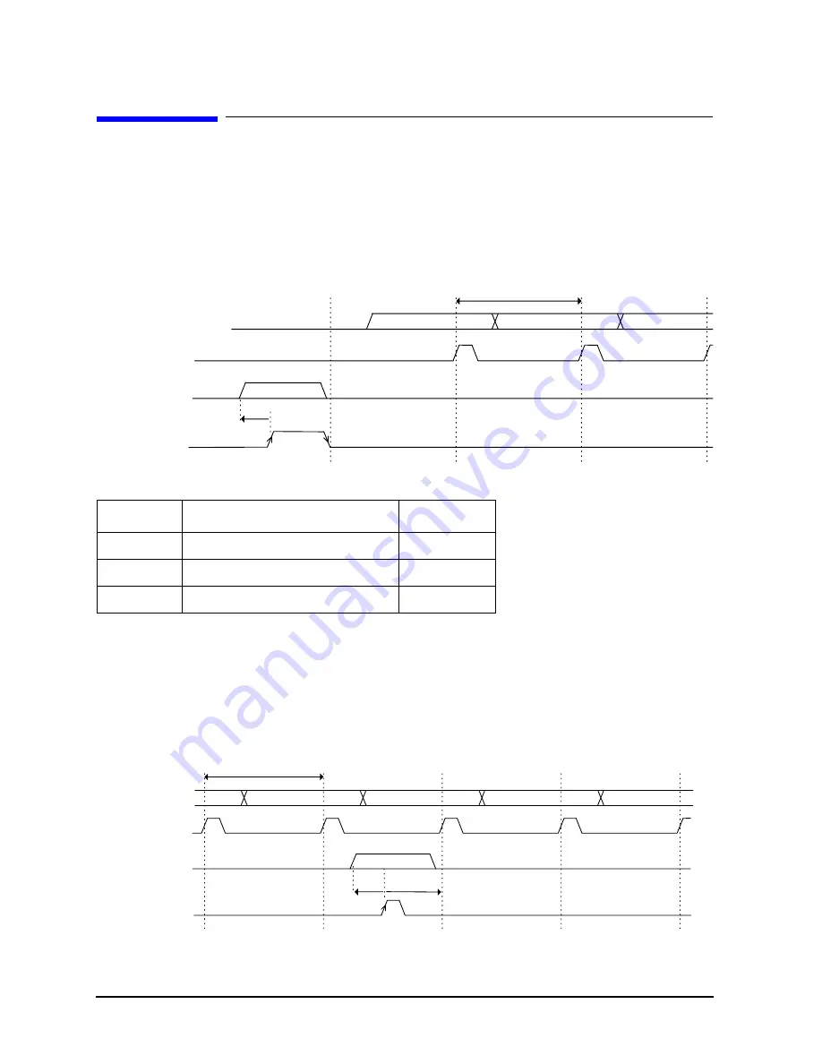
Once the ARB has been “armed”, it will wait until a trigger is received on patt_trig_in2. 
The rising edge of patt_trig_in2 will latch in the external 8 bit segment number input on 
pdata(7..0). The falling edge of patt_trig_in2 will “trigger” the externally defined waveform 
segment to be played continuously. Refer to timing diagram below.

External Segment Switch Continuous

In this mode, the next segment is determined by the external 8 bit segment number 
pdata(7..0). The timing of the segment switch is controlled by the input strobe 
patt_trig_in2. The next segment number is strobed into the ARB on the rising edge of 
patt_trig_in2. The current segment will complete before switching to the next segment. 
This segment will play continuously until a new segment is strobed in by patt_trig_in2. 

Minimum

t1

Segment period

150 samples

t2

Segment setup time

150 samples

t3

pdata setup time

50 ns

I/Q_out

symbol_

sync_out

pdata(7..0)

6

6

6

6

Load

External

Segment

Trigger

t1

t3

patt_trig_in2

I/Q_out

pdata(7..0)

patt_trig_in2

t3

6

2

2

6

6

2

t2

Load

External

Segment

t1

symbol_

sync_out

Summary of Contents for E4438C

Page 1: ...Agilent Technologies E4438C Option SP2 User s and Service Guide ...

Page 2: ......

Page 3: ...Agilent Technologies E4438C Option SP2 User s and Service Guide Manufacturing Part Number E4400 90635 Printed in USA November 2005 Copyright 2005 Agilent Technologies Inc All rights reserved ...

Page 4: ...ENT THAT CONFLICT WITH THESE TERMS THE WARRANTY TERMS IN THE SEPARATE AGREEMENT WILL CONTROL DFARS Restricted Rights Notice If software is for use in the performance of a U S Government prime contract or subcontract Software is delivered and licensed as Commercial computer software as defined in DFAR 252 227 7014 June 1995 or as a commercial item as defined in FAR 2 101 a or as Restricted computer...

Page 5: ...uld result in damage to or destruction of the instrument Do not proceed beyond a caution sign until the indicated conditions are fully understood and met Definitions Specifications describe the performance of parameters covered by the product warranty temperature 0 to 55 C unless otherwise noted Typical describes additional product performance information that is not covered by the product warrant...

Page 6: ...iv ...

Page 7: ... Continuous with Delays 7 External Segment Switch Continuous switched on consecutive segments 7 AUX I O Pinout 8 Segment Size is too Small in Relation to the Trigger Signal 9 Safety and Regulatory Information 11 Introduction 11 Before Applying Power 11 Connector Care and Cleaning 11 Statement of Compliance 11 Declaration of Conformity 11 Shipping Instructions 11 Compliance with Canadian EMC Requir...

Page 8: ...Contents 2 Contents ...

Page 9: ...User s and Service Guide 1 E4438C Option SP2 ...

Page 10: ...te the existing ARB Waveform Sequence feature In this original mode of operation Waveform Segments are listed linearly within a Waveform Sequence Contents table on the Unit Interval UI The ARB player then plays advances these segments in a LINEAR incremental order subject to a set of qualifying Segment Advance triggers Dynamic Segment Switching Dynamic Segment Switching will allow the arbitrary or...

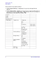
Page 11: ...f the strobe signal before beginning to play the next segment User Interface Typeface Key Conventions The following key conventions are used throughout this document HARDKEYS are labeled front panel keys SOFTKEYS are unlabeled key whose function is indicated on the instrument display Keyboard and Display From the ARB Trigger menu Segment Advance will be selected as before A further selection of Tr...

Page 12: ... access to the Trigger Setup Trigger Source menu which will default to Ext Ext Source Patt Trig In 2 Ext Polarity Neg Continuous Single Gated Segment Advance Trigger Setup Trigger Source Trigger Key Bus Ext Ext Source Patt Trig In 1 Patt Trig In 2 Ext Delay Off On Ext Delay Time 10 ns to 40 s Continuous Mode Free Run Trigger Run Reset Run Retrigger Mode Off On Immediate Segment Advance Mode Single...

Page 13: ...segments Segment numbering or indexing is therefore implicit to Pulsebuilder such that there is no attempt to enhance the UI with segment numbering information Segment Order SOURce RADio 1 ARB TRIGger TYPE SADVance SORDder LINear DYNamic SOURce RADio 1 ARB TRIGger TYPE SADVance SORDder Trigger Hold Off SOURce RADio 1 ARB TRIGger TYPE SADVance THOFf ON OFF 1 0 SOURce RADio 1 ARB TRIGger TYPE SADVan...

Page 14: ...e next segment is determined by the external 8 bit segment number pdata 7 0 The timing of the segment switch is controlled by the input strobe patt_trig_in2 The next segment number is strobed into the ARB on the rising edge of patt_trig_in2 The current segment will complete before switching to the next segment This segment will play continuously until a new segment is strobed in by patt_trig_in2 M...

Page 15: ...ext segment plays triggered by the falling edge on patt_trig_in2 This segment will then play continuously until a new segment is strobed in by patt_trig_in2 External Segment Switch Continuous switched on consecutive segments The following diagram illustrates the segment being switched on consecutive segments I Q_out pdata 7 0 t3 6 2 6 6 2 2 t2 Load External Segment Trigger t1 patt_trig_in2 symbol_...

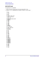
Page 16: ...ble and is located on a BNC on the rear panel 1 N A 2 GND 3 GND 4 N A 5 SYMBOL SYNC OUT 6 DATA CLOCK OUT 7 DATA OUT 8 PARALLEL DATA CLOCK 9 PDATA 8 10 GND 11 GND 12 GND 13 GND 14 GND 15 PDATA 1 16 ALT PWR IN 17 PATT_TRIG_IN 2 18 EVENT 4 19 EVENT 3 20 N A 21 N A 22 N A 23 GND 24 GND 25 GND 26 GND 27 GND 28 PDATA 7 29 PDATA 6 30 PDATA 5 31 PDATA 4 32 PDATA 3 33 PDATA 2 34 GND 35 GND 36 GND 37 GND ...

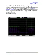
Page 17: ...le size is too short in relation to the trigger pulse minimum specifications Refer to Technical Specification on page 6 which states that the segment setup time should be 150 samples minimum As shown in the graphic below instead of a clean change over to the sinusoid the sawtooth segment is seen to continue on the falling edge of the trigger signal Trigger Pulse Period 17 µs Segment Sizes 200 Sa 2...

Page 18: ...10 User s and Service Guide E4438C Option SP2 Technical Specification This is what should happen when the Trigger Pulse period is adjusted Trigger Pulse Period 22 µs Segment Sizes 200 Sa 2 µs ...

Page 19: ...nnect the Agilent Technologies model product from mains before cleaning Use a dry cloth or one slightly dampened with water to clean the external case parts Do not attempt to clean internally Statement of Compliance This instrument has been designed and tested in accordance with IEC Publication 1010 Safety Requirements for Electronic Measuring Apparatus and has been supplied in a safe condition Th...

Page 20: ...orme NMB du Canada Compliance with German Noise Requirements This is to declare that this instrument is in conformance with the German Regulation on Noise Declaration for Machines Laermangabe nach der Maschinenlaermrerordnung 3 GSGV Deutschland Acoustic Noise Emission Geraeuschemission LpA 70 dB Lpa 70 dB Operator Position am Arbeitsplatz Normal Operation normaler Betrieb per ISO 7779 nach DIN 456...

Page 21: ...duct provided with a protective earthing ground incorporated in the power cord The mains plug shall be inserted only into a socket outlet provided with a protective earth contact Any interruption of the protective conductor inside or outside the instrument is likely to make the instrument dangerous Intentional interruption is prohibited WARNING The power cord is connected to internal capacitors th...

Page 22: ...tions are fully understood and met Cautions applicable to this instrument are CAUTION Always use the three prong ac power cord supplied with this instrument Failure to ensure adequate earth grounding by not using this cord can cause instrument damage CAUTION This instrument has autoranging line voltage input be sure the supply voltage is within the specified range CAUTION Ventilation Requirements ...

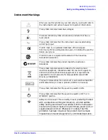
Page 23: ...symbol indicates separate collection for electrical and electronic equipment mandated under EU law as of August 13 2005 All electric and electronic equipment are required to be separated from normal waste for disposal Reference WEEE Directive 2002 96 EC This text indicates that the instrument is an Industrial Scientific and Medical Group 1 Class A product CISPR 11 Clause 4 This symbol indicates th...

Page 24: ...65 6755 1214 South Korea tel 080 778 0011 fax 080 778 0013 Taiwan tel 0800 047 669 fax 0800 047 667 fax 886 3492 0779 Thailand tel 66 2 267 5913 tel 1 800 2758 5822 fax 1 800 653 336 Europe Austria tel 0820 87 44 11 fax 0820 87 44 22 Belgium tel 32 0 2 404 9340 fax 32 0 2 404 9395 Denmark tel 45 7013 1515 fax 45 7013 1555 Finland tel 358 0 10 855 2100 fax 358 0 10 855 2923 France tel 0825 010 700 ...

Page 25: ...培训课程三个类别共 30 门视频培训课程和 3 本图书教材 旨在 引领学员全面学习一个射频工程师需要熟悉 理解和掌握的专业知识和 研发设计能力 通过套装的学习 能够让学员完全达到和胜任一个合格 的射频工程师的要求 课程网址 http www edatop com peixun rfe 110 html 手机天线设计培训视频课程 该套课程全面讲授了当前手机天线相关设计技术 内容涵盖了早期的 外置螺旋手机天线设计 最常用的几种手机内置天线类型 如 monopole 天线 PIFA 天线 Loop 天线和 FICA 天线的设计 以及当前 高端智能手机中较常用的金属边框和全金属外壳手机天线的设计 通 过该套课程的学习 可以帮助您快速 全面 系统地学习 了解和掌 握各种类型的手机天线设计 以及天线及其匹配电路的设计和调试 课程网址 http www edatop com peixun antenna...

Page 26: ...让您的 HFSS 学习更加轻松顺畅 课程网址 http www edatop com peixun hfss 11 html ADS 学习培训课程套装 该套装是迄今国内最全面 最权威的 ADS 培训教程 共包含 10 门 ADS 学习培训课程 课程是由具有多年 ADS 使用经验的微波射频与通信系统 设计领域资深专家讲解 并多结合设计实例 由浅入深 详细而又全面 地讲解了 ADS 在微波射频电路设计 通信系统设计和电磁仿真设计方面 的内容 能让您在最短的时间内学会使用 ADS 迅速提升个人技术能力 把 ADS 真正应用到实际研发工作中去 成为 ADS 设计专家 课程网址 http www edatop com peixun ads 13 html 我们的课程优势 成立于 2004 年 10 多年丰富的行业经验 一直致力并专注于微波射频和天线设计工程师的培养 更了解该行业对人才的要求 经验丰富...

Reviews: