background image

Installation Note

Part Number E4440-90255
Printed in USA

August 2004

Agilent PSA Series Spectrum Analyzers
Option 124 Y-Axis Video Output 
Retrofit Kit

Summary of Contents for E4440-90255

Page 1: ...Installation Note Part Number E4440 90255 Printed in USA August 2004 Agilent PSA Series Spectrum Analyzers Option 124 Y Axis Video Output Retrofit Kit ...

Page 2: ...d to this material including but not limited to the implied warranties of merchantability and fitness for a particular purpose Agilent Technologies shall not be liable for errors contained herein or for incidental or consequential damages in connection with the furnishing performance or use of this material Copyright 2004 Agilent Technologies Inc ...

Page 3: ...t to a rear panel BNC connector NOTE This option is licensed for one instrument model number serial number combination The license key will only install on the designated instrument NOTE The instrument must be performance tested to ensure that the instrument meets specifications following the hardware installation NOTE The instrument firmware revision must be A 06 00 or greater to allow installati...

Page 4: ...0 Windows XP Professional Firmware A 0 6 00 or later Download the latest revision form http www agilent com find psa_firmware or order the Firmware Update kit Depending on your model number the firmware update kit is ordered as Order E444xAU Qty 1 Option UE2 Qty 1 where the x is the last digit of the model number For example E4440AU option UE2 Quantity Description Agilent Part Number 1 Installatio...

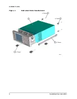
Page 5: ...irections in the kit Remove the Outer Case CAUTION If the instrument is placed on its face during any of the following procedures be sure to use a soft surface or soft cloth to avoid damage to the front panel keys or input connector 1 Disconnect the instrument from ac power 2 Refer to Figure 1 Remove the two handles on the sides of the instrument as shown Use the T 20 driver to loosen the screws t...

Page 6: ...6 Installation Note E4440 90255 Installation Procedure Figure 1 Instrument Outer Case Removal ...

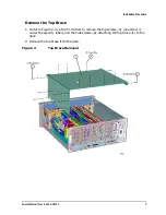
Page 7: ...ure Remove the Top Brace 1 Refer to Figure 2 Use the T 10 driver to remove the top screws 3 one screw is under the security label and the side screws 2 attaching the top brace 1 to the deck 2 Remove the top brace from the deck Figure 2 Top Brace Removal ...

Page 8: ...since it will be replaced 3 Install the A7 Digital IF assembly from the kit Re attach the gray cable W10 removed in step 2 to P3 Cable designator P3 and GRAY 8 are silk screened on the board 4 On the instrument rear panel locate the Video Out hole Remove the hole plug and insert the BNC end of W67 BNC to MCX Video Output cable contained in the kit You will be able to insert the BNC connector throu...

Page 9: ...lace the side screws Torque to 101 Ncm 9 in lb 3 Refer to Figure 1 Slide the instrument cover back onto the deck from the rear The seam on the cover should be on the bottom Be sure the cover seats into the gasket groove in the front frame 4 Replace the four rear feet onto the rear of the instrument Torque to 236 Ncm 21 in lb 5 Use the T 20 driver to replace the handles Torque to 236 Ncm 21 in lb 6...

Page 10: ... and Option This will activate the alpha editor menu Use the alpha editor and the front panel numerical keypad to enter the option designator 124 Press the Enter key Note that 124 now appears on the Option key 4 Press License Key The license key number is a hexadecimal number that will require the entry of both letters and numbers Use the alpha editor and the front panel numerical keypad to enter ...

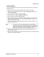
Page 11: ... Amplitude and adjusting the reference level until the signal is as close as possible to exactly mid screen The voltmeter should read 0 5 volts 7 Adjust the reference level to place the signal exactly on the top graticule line The voltmeter should read 1 V NOTE The signal trace cannot be displayed above the top graticule line However the analyzer will measure signals above the top graticule line T...

Page 12: ...re no adjustments on the Digital IF assembly NOTE This procedure requires the use of the PSA Series Performance Tests and Adjustment Software For assistance contact your nearest Agilent Technologies Sales and Service Office To find your local Agilent office access the following URL or call the following telephone number http www agilent com find assist 1 800 452 4844 8am 8pm EST Performance Test N...

Reviews: