40
Chapter 4
Troubleshooting
Function Specific Troubleshooting
Function Specific Troubleshooting
If the E4980A exhibits a failure symptom that is related to a specific function or control
such as a front panel key control, display, data storage, remote control interface, external
trigger, isolate the trouble using the Function Specific Troubleshooting procedures
described below. The major functions of the E4980A and the troubleshooting procedure for
each function are shown in Table 4-5.
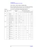
Table 4-5
Major functions and troubleshooting procedures
Function
Description
Troubleshooting
Front panel keys
All the E4980A functions can be set and controlled
via the front panel keys.
Refer to “To Check the Front
Panel” on page 41.
LCD display
Almost all the information including the
measurement value, setup state, result data
processing, menu bar, softkey label and others are
indicated on the LCD display.
Refer to “To Check the
LCD” on page 41.
Front USB port
The USB port is used to save data in a USB
memory. The LED for USB lights up while
accessing the USB memory.
Refer to “To Check the Front
USB port” on page 41.
External trigger input
The external trigger input terminal (BNC) on the
rear panel allows an external trigger source to be
used for measurement trigger.
Refer to “To Check the
External Trigger Input” on
page 42.
LAN port
The LAN interface port on the rear panel allows
the E4980A to be connected to 10/100 Base-T
Ethernet.
Refer to “To Check the
LAN” on page 42.
GPIB Interface
The GPIB compatibility allows the E4980A to be
operated as a talker/listener on IEEE 488 interface
bus.
Refer to “To Check the
GPIB” on page 44.
USB (USBTMC)
Interface
Through this port, you can control the E4980A via
external controllers. It is equivalent to control via
GPIB.
Refer to in “To Check the
USB (USBTMC) Interface
Card” on page 45.
Handler interface
(Option E4980A-201)
The interface is for data exchange with an
automatic machine (handler) used on production
line.
Refer to in “To Check the
Handler Interface Function
(Option 201 only)” on
page 45.
Scanner interface
(Option E4980A-301)
The interface to connect a scanner to perform up to
128 sets of multi-channel correction and
measurements.
Refer to in “To Check the
Scanner Interface Function
(Option 301 only)” on
page 49.
Bias current interface
(Option E4980A-002)
The interface to connect the 42841A (Bias Current
Source).
Refer to in “To Check the
Bias Current Interface
Function (Option 002 only)”
on page 53.
Summary of Contents for E4980A
Page 12: ...12 Contents ...
Page 60: ...60 Chapter4 Troubleshooting Performance test failure troubleshooting ...
Page 86: ...86 Chapter5 Replaceable Parts Replaceable Parts List ...
Page 126: ...126 Chapter6 Replacement Procedure Display Interface Replacement ...
Page 136: ...136 AppendixB Firmware Update Update the E4980A firmware using USB cable ...
Page 140: ...140 AppendixC Power Requirement Power Requirements Figure C 3 Power Cable Supplied ...
Page 152: ...152 AppendixD Error Messages Error number 45 ...


