Chapter 6
89
Replacement Procedure
Required Tools
6. Re
placem
ent Pro
c
e
d
u
re
Required Tools
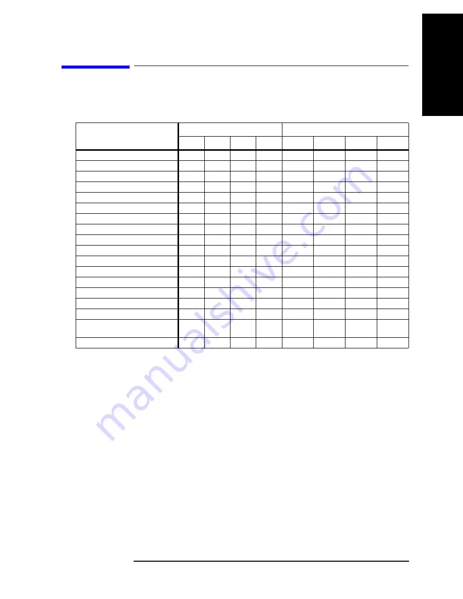
The following tools are required for repair of E4980A.
Table 6-1
Required Tools
Assembly
Torque screwdriver
Box torque wrench
T6
T8
T10
T20
5.5 mm
7 mm
3/8 in.
5/8 in.
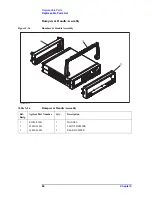
3/4 Rack Module Top
A3 Analog Daughter Board
A2 Analog Board
Front Panel Assembly
Option Interface
PPMC PCA
A1 Mother Board
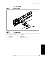
Power Supply Assembly
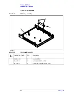
Base Plate
Rear Panel Assembly
FAN Assembly
GPIB Cable
Power Inlet Assembly
PCA E4980 USB
Binding Post Sgl
Inverter
Front Panel, Key Pad, and Key Flex
Circuit
Display Interface
Summary of Contents for E4980A
Page 12: ...12 Contents ...
Page 60: ...60 Chapter4 Troubleshooting Performance test failure troubleshooting ...
Page 86: ...86 Chapter5 Replaceable Parts Replaceable Parts List ...
Page 126: ...126 Chapter6 Replacement Procedure Display Interface Replacement ...
Page 136: ...136 AppendixB Firmware Update Update the E4980A firmware using USB cable ...
Page 140: ...140 AppendixC Power Requirement Power Requirements Figure C 3 Power Cable Supplied ...
Page 152: ...152 AppendixD Error Messages Error number 45 ...


