background image

 102

Chapter 6


Replacement Procedure

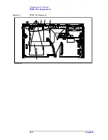
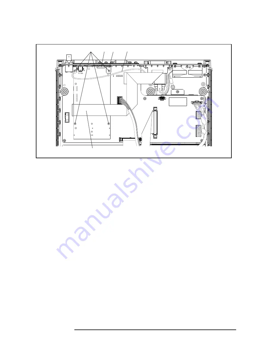
PPMC PCA Replacement

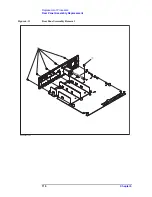
Figure 6-7 

PPMC PCA Removal 

㪼㪋㪐㪏㪇㪸㫊㪼㪈㪇㪉㪇

Summary of Contents for E4980A

Page 1: ...This manual applies directly to instruments that have the firmware revision A 01 00 or higher For additional information about firmware revisions see Appendix A Agilent Part No E4980 90120 August 2010 Advanced Test Equipment Rentals www atecorp com 800 404 ATEC 2832 Established 1981 ...

Page 2: ...ompany Limited Portions Copyright 1996 Microsoft Corporation All rights reserved Copyright 2006 2007 2008 2010 Agilent Technologies Manual Printing History The manual s printing date and part number indicate its current edition The printing date changes when a new edition is printed Minor corrections and updates that are incorporated at reprint do not cause the date to change The manual part numbe...

Page 3: ...ments are to be confirmed by the builder of the system Ground the Instrument To avoid electric shock the instrument chassis and cabinet must be grounded with the supplied power cable s grounding prong DO NOT Operate in an Explosive Atmosphere Do not operate the instrument in the presence of inflammable gasses or fumes Operation of any electrical instrument in such an environment clearly constitute...

Page 4: ...to refer to the instrument manual Alternating current Direct current On Supply Off Supply In position of push button switch Out position of push button switch Frame or chassis terminal A connection to the frame chassis of the equipment which normally include all exposed metal structure Stand by WARNING This warning sign denotes a hazard It calls attention to a procedure practice condition or the l...

Page 5: ...to the implied warranties of merchantability and fitness for a particular purpose Agilent shall not be liable for errors or for incidental or consequential damages in connection with the furnishing use or performance of this document or any information contained herein Should Agilent and the user have a separate written agreement with warranty terms covering the material in this document that conf...

Page 6: ...y key on the front panel or external keyboard labeled Sample key may be omitted Sample menu button box Indicates a menu button box on the screen labeled Sample which can be selected executed by clicking menu button or box may be omitted Sample 1 Sample 2 Sample 3 Indicates a sequential operation of Sample 1 Sample 2 and Sample 3 menu button or box may be omitted ...

Page 7: ...ent Safety Considerations 22 Warm up for Adjustment 22 Required Equipment 22 Required Adjustment after Replacing Assembly 23 Writing ID 23 Write Null Phase Track Default Data 23 Null DC Offset Adjustment 23 Null ADC DC Offset Adjustment 23 ADC Linearity Adjustment 23 DC Bias Adjustment 24 DC Level V Monitor Adjustment 24 DC Level I Monitor Adjustment 24 DC Source Adjustment 24 DCR Adjustment 24 Im...

Page 8: ...57 Recommended adjustment for performance test failure 57 Adjustment failure troubleshooting 58 Performance test failure troubleshooting 59 5 Replaceable Parts Ordering Information 62 Direct Mail Order System 62 Exchange Assemblies 62 Replaceable Parts List 63 Power Cables and Plug Configurations 63 Top View Major Assemblies 64 Top View Cables 66 Top View Miscellaneous Parts 68 Top View Tested PCA...

Page 9: ...cedure 101 Replacement Procedure 101 A1 Mother Board Replacement 103 Tools Required 103 Removal Procedure 103 Replacement Procedure 103 Power Supply Assembly Replacement 105 Tools Required 105 Removal Procedure 105 Replacement Procedure 105 Base Plate Replacement 107 Tools Required 107 Removal Procedure 107 Replacement Procedure 107 Rear Panel Assembly Replacement 109 Tools Required 109 Removal Pr...

Page 10: ...re 122 Display Interface Replacement 124 Tools Required 124 Removal Procedure 124 Replacement Procedure 124 7 Post Repair Procedures Post Repair Procedures 128 A Manual Changes Manual Changes 132 B Firmware Update Update the E4980A firmware using USB GPIB interface 134 Required Equipment 134 How to update E4980A firmware using USB GPIB interface 134 Update the E4980A firmware using USB cable 135 R...

Page 11: ...Contents 11 D 143 E 144 F 144 G 145 H 145 I 145 M 146 N 146 O 146 P 147 Q 147 R 148 S 148 T 148 U 148 V 149 Warning Message 150 Numeric 150 A 150 C 150 I 150 S 151 ...

Page 12: ...12 Contents ...

Page 13: ... 4 Chapter Title 5 Chapter Title 1 General Information This Service Guide is a guide to servicing the E4980A 20 Hz to 2 MHz Precision LCR Meter The Service Guide provides information about performance test adjustment troubleshooting and repairing the E4980A ...

Page 14: ... to isolate a faulty assembly in the E4980A Chapter 5 Replaceable Parts This chapter contains information for ordering replacement parts for the E4980A Chapter 6 Replacement Procedure This chapter provides procedure for removing and replacing the major assemblies in the E4980A Chapter 7 Post Repair Procedures This chapter lists the procedures required to verify the E4980A operation after an assemb...

Page 15: ...have a different manual part number This sheet contains change information that explains how to adapt the manual to the newer instrument In addition to change information the supplement may contain information for correcting errors Errata in the manual To keep this manual as current and accurate as possible Agilent Technologies recommends that you periodically request the latest Manual Changes sup...

Page 16: ...42030A 1 P A 4TP Open Termination No Substitute Agilent 42090A 1 P A 4TP Short Termination No Substitute Agilent 42091A 1 P A Test Leads BNC 1 m No Substitute Agilent 16048A 1 P A Test Leads BNC 2 m No Substitute Agilent 16048D 1 P A Test Leads BNC 4 m No Substitute Agilent 16048E 1 P A DC Power Supply 5V 0 1A Agilent E3610A 1 T Handler Simulator No Substitute p n 04278 65001 1 T Scanner Simulator...

Page 17: ...17 1 Chapter Title 3 Chapter Title 4 Chapter Title 5 Chapter Title 2 Performance Test 2 Performance Test This chapter provides the outline of the E4980A performance tests ...

Page 18: ...nds on maintenance and the environmental conditions under which the instrument is used You may find that the interval could be shortened or lengthened however such a decision should be based on substantial quantitative data Test Equipment Required The required equipment for the performance test is listed in Table 1 1 Use only calibrated equipment when doing the performance test Table 2 1 List of t...

Page 19: ...cy Test Description This test checks the DC source level accuracy of the E4980A DC source port output signal 3 DC Bias Level Accuracy Test Description This test checks the DC bias level accuracy of the E4980A DC bias signal 4 DC Bias V Level Monitor Accuracy Test Description This test checks the DC bias V level monitor accuracy of the E4980A Option 001 only 5 DC Bias I Level Monitor Accuracy Test ...

Page 20: ...Description 8 Impedance Measurement Accuracy Test Description This test checks the impedance measurement accuracy of the E4980A 9 DCR Measurement Accuracy Test Description This test checks the DCR measurement accuracy of the E4980A Option 001 only ...

Page 21: ... This chapter provides the adjustment information for the E4980A to ensure that it is within its specifications The adjustment must be performed Agilent s qualified service personnel If you need the adjustment for your E4980A it should be sent to the nearest Agilent Technologies service office ...

Page 22: ...ide or outside the equipment or disconnection of the protective ground terminal can make the instrument dangerous Intentional interruption of the protective ground system for any reason is prohibited Warm up for Adjustment Warm up the E4980A for at least 30 minute before performing any of the following Adjustment procedures to ensure proper results and correct instrument operation Required Equipme...

Page 23: ...e is to write the null phase track default data into A2 board Null DC Offset Adjustment The purpose of this procedure is to adjust the null dc offset of the A2 board Null ADC DC Offset Adjustment The purpose of this procedure is to adjust the null adc dc offset of the A2 board ADC Linearity Adjustment The purpose of this procedure is to ajust ADC non linearity of the A2 board Table 3 1 Required Ad...

Page 24: ...pose of this procedure is to adjust the DC Level I Monitor DC Source Adjustment The purpose of this procedure is to adjust the DC Source level DCR Adjustment The purpose of this procedure is to adjust the DCR measurement Impedance Adjustment The purpose of this procedure is to adjust the impedance measurement AC Level Monitor Adjustment The purpose of this procedure is to adjust the AC level monit...

Page 25: ...25 4 Troubleshooting 4 Troubleshooting This chapter provides the procedure to isolate a faulty assembly in the E4980A ...

Page 26: ...ening of covers or removal of parts is likely to expose dangerous voltages Disconnect the instrument from its power supply beforehand CAUTION Many of the assemblies in the instrument are very susceptible to damage from ESD electrostatic discharge Perform the following procedures only at a static safe workstation and wear a grounding strap CAUTION DO NOT operate without following instructions Progr...

Page 27: ...e LED should go out and the yellow green LED should come on Also the fan should start rotating In case of unexpected results go to Power On Sequence Troubleshooting on page 29 Step 2 Check the display The power on test is executed once automatically before the measurements start If the power on test fails go to Troubleshooting Using Service Function on page 32 If one of the following error message...

Page 28: ...Yes No Yes No Yes Power on Power on test Go to Troubleshooting Using Service Function Power on test pass Yes No End Performance test Go to Performance Test Failure Troubleshooting Performance test pass Yes No No In case of display scan brightness and color problems Display and Boot up Problems Problems on Measurement Performance and Measurement Result Problems on Front Panel LCD Display Front USB ...

Page 29: ... they are all correct For more information about the line cord and power fuse see the Power Requirements in Appendix B Check the Power Supply Unit Output Step 1 Remove the E4980A s outer cover Step 2 Turn the E4980A power on Step 3 Measure the output voltage 3 3 5 12 12 V of the power supply unit using a voltmeter with a small probe The location of each voltage connector on the A1 board and A3 boa...

Page 30: ...the voltmeter reading is not within the following limits replace the power supply unit 㪼㪋㪐㪏㪇㪸㫊㪼㪈㪇㪋㪌 P6 P5 P4 P1 12V 12V 3 3V 5V J11 P3 P4 P5 P1 3 3V P3 12V P6 12V 3 3V 12V 5V J6 J5 P501 Table 4 1 Power Supply Unit Output supply Range 3 3 V 3 2 to 3 4 5 V 4 8 to 5 2 12 V 11 4 to 12 6 12 V 11 4 to 12 6 ...

Page 31: ... board and the relevant cable 6 The LED on the display interface board should blink If the LED doesn t blink check the display interface board the A1 board and the relevant cable 7 Three LEDs for DC Source DC Bias and USB should go out 8 The firmware revision and hardware option information along with copyright declaration should be displayed If nothing is displayed check the LCD display interface...

Page 32: ... tests as shown in Table 4 4 If the power on test is failed an error code or an error message is also displayed You can identify a failure section with the error code or the error message The error code or error message is related to each test group as shown in Table 4 4 For example the first item of the error code is for CPU test group second item is for System test group and seventh item is for ...

Page 33: ... Description SYSTEM Checks the entire system A1 A2 A3 boards system calibration data and so on USER DATA Checks the GPIB LAN configurations instrument configuration information instrument calibration data and scanner calibration data BATTERY Checks the internal batteries KEY Checks the font panel keys Visual checks only no result shown on screen DISPLAY Checks the font panel LEDs and LCD Visual ch...

Page 34: ...rform by using the INCR and DECR softkeys Step 7 Press EXECUTE TEST START 2 in Figure 4 4 to execute the selected test item Figure 4 4 Self test screen and procedure SERVICE Page The results of the power on test or the self test SYSTEM USER DATA and BATTERY can be saved into a USB memory Pressing the System key followed by the SERVICE softkey opens the SERVICE page This page is read only HANDLER I...

Page 35: ...support and repair by Agilent Technologies but will never be used for any other purposes Figure 4 5 SERVICE Page Monitor Information The SERVICE page displays the following monitor information which cannot be edited on the SERVICE page 㪼㪋㪐㪏㪇㪸㫌㪼㪈㪈㪋㪎 㪑㩷㩷㪤㫆㫅㫀㫋㫆㫉 Table 4 3 Monitor Information Description POWER ON Displays how many times E4980A have been started up and its cumulative power on time SYSC...

Page 36: ...lug a USB memory stick into the front USB port Step 2 Press System Step 3 Press the SERVICE softkey Step 4 Press the MORE softkey Step 5 Press the SAVE SYS INFO softkey Step 6 While the data is being saved a PROCESSING message is shown on the display When the data has been saved into the USB memory a Storing data completed message appears in the system message area Example of the System Informatio...

Page 37: ...883E 00 A1 4 3 359375000E 00 A1 5 2 504882813E 00 A1 6 5 090893269E 00 A2 1 2 337981556E 04 A2 2 4 294419530E 01 A2 3 4 937164751E 01 A2 4 4 625371247E 01 A2 5 4 599838385E 01 A2 6 3 438261555E 01 A3 1 4 189105189E 05 A3 2 8 715481204E 01 A3 3 8 746015586E 01 A3 4 7 700712127E 01 A3 5 2 887844449E 01 USER 1 0 USER 2 0 USER 3 0 USER 4 0 BATT 1 3 247070313E 00 3 750000000E 01 4 474563461E 01 4 40480...

Page 38: ... failure troubleshooting information Test group Test No Test Name Error Code Message Probable faulty board assembly A1 A2 A3 Bias IF Handler Scanner PPMC CPU 1 CPU Test 1 ffff 2 CPU Test 1 ff System 1 A1 FPGA check 0x01 2 A2 FPGA check 0x02 3 A1 Revision check 0x04 4 A2 Revision check 0x08 5 A3 Revision check 0x10 Data 1 System Data 0x01 2 SysCal Data 0x02 3 Flash File system check 0x04 4 Test Lim...

Page 39: ..._P3V 0x04 4 A2_DCBUS_P10V 0x08 5 A2_DCBUS_M10V 0x10 6 A2_DCBUS_TEMP 0x20 A3 1 A3_DCBUS_GND 0x01 2 A3_DCBUS_N50V 0x02 3 A3_DCBUS_P50V 0x04 4 A3_DCBUS_N12V 0x08 5 A3_DCBUS_TEMP 0x10 User 1 User Data User Data Lost 2 State Data State Data Lost 3 Correction Data Corr Data Lost 4 Scanner Correction Data Scanner Data Lost Battery 1 A1_DCBUS_BATT ERY Battery Low Table 4 4 Power on test self test failure ...

Page 40: ...nal trigger input The external trigger input terminal BNC on the rear panel allows an external trigger source to be used for measurement trigger Refer to To Check the External Trigger Input on page 42 LAN port The LAN interface port on the rear panel allows the E4980A to be connected to 10 100 Base T Ethernet Refer to To Check the LAN on page 42 GPIB Interface The GPIB compatibility allows the E49...

Page 41: ...subsided in the panel To Check the LCD Procedure Step 1 Press System SELF TEST Step 2 Use the cursor key to highlight the selection item to the right of TEST No Step 3 Select 5 DISPLAY using the INCR or DECR softkey Step 4 Press EXECUTE TEST START The whole of the LCD screen turns Red Green Blue Black and White every 2 seconds Step 5 To exit the DISPLAY test press TEST STOP and then press Return I...

Page 42: ...USB port or A1 board is suspected Also check the cable between the USB port and A1 board To Check the External Trigger Input Procedure Step 1 Press Preset CLEAR SETTING OK to initialize the E4980A Step 2 Press Meas Setup Step 3 Using the cursor keys select the TRIG field and then select EXTsoftkey Step 4 Press Display Format Step 5 Connect a BNC Short or 50 termination to the Ext Trig connector on...

Page 43: ...indow double click Network The Network dialog box will appear In the Configuration tab select TCP IP display it in revers video and press the Properties button c The dialog box appears If Specify an IP address has been selected record the IP address and subnet mask d If the Obtain an IP address automatically has been selected select the Specify an IP address Enter the IP address xxx xxx xxx y and ...

Page 44: ...gure 4 7 shows an example of normal result that indicates the IP address packet size and a response time counted by the computer The ping command is repeated 4 times Figure 4 7 Example of normal ping command test result If the E4980A doesn t return the response the external computer displays a message of Request timed out as shown in Figure 4 8 In this case a failure in the PPMC PCA is suspected F...

Page 45: ... to discharge Step 2 Remove the Handler Interface Board according to the procedure for describing in Handler Interface Chapter of the User s Guide NOTE The interface board contains electronic components that can be damaged by static electricity through electrostatic discharge ESD To prevent ESD damage maintain frequent contact with any bare sheet metal surface on the chassis A grounding wrist stra...

Page 46: ...ch Settings 㪼㪋㪐㪏㪇㪸㫊㪼㪈㪇㪋㪐 㪡㪧㪉 㪡㪧㪈 㪦㪥 㪪㪈 㪦㪝㪝 Table 4 7 Internal jumper settings Jumper number Jumper position 1 1 The factory default setting is position N shown in the table above JP1 1 2 3 N 4 JP2 1 2 3 N 4 Table 4 8 Bit switch S1 settings Bit number 1 Factory default settings 1 Off 2 Off ...

Page 47: ...er Interface Function Test Setup Step 7 Press System Step 8 Press the SELF TEST softkey to display the SELF TEST page 3 On 4 Off 5 Off 6 Off 7 N A 8 N A 1 The bit numbers referenced in this table are the numbers printed on the bit switch S1 of the handler interface board Table 4 8 Bit switch S1 settings Bit number 1 Factory default settings 㪼㪋㪐㪏㪇㪸㫊㪼㪈㪇㪌㪇 USB LAN Trigger GPIB LINE 115V 230V 50 60Hz ...

Page 48: ... light in the sequence shown in Figure 4 11 Figure 4 11 Handler Interface Function Check Step 13 Press the TEST STOP softkey NOTE Do not execute any SELF TEST except for the Handler Interface Test or the E4980A will become inoperative Step 14 Return the jumper and switch settings on the handler interface board to their original settings Softkey Function INCR Increments the test number of the Test ...

Page 49: ...e interface board contains electronic components that can be damaged by static electricity through electrostatic discharge ESD To prevent ESD damage maintain frequent contact with any bare sheet metal surface on the chassis A grounding wrist strap or similar device is useful for this purpose Handle the board carefully at all times Avoid touching electronic components or circuit paths NOTE Before p...

Page 50: ...s S1 and S2 can be identified by the labels S1 and S2 on the scanner 㪼㪋㪐㪏㪇㪸㫊㪼㪈㪇㪌㪉 10 10 㪦㪥 㪦㪝㪝 㪪㪉 㪦㪥 㪦㪝㪝 㪪㪈 Table 4 10 Setting Bit Switch S1 Bit Default 1 1 1 For bits 1 to 3 of bit switch S1 only one bit can be turned on at one time On 2 1 Off 3 1 Off 4 On Table 4 11 Setting Bit Switch S2 Bit Default 1 8 On ...

Page 51: ... Figure 4 13 Step 7 Connect the 1 k standard to the UNKNOWN terminal on the E4980A s front panel Step 8 Turn the E4980A ON Step 9 Press System Step 10 Press the SELF TEST softkey to display the SELF TEST page Step 11 Use the CURSOR arrow keys to move the cursor to the TEST MENU field Step 12 Use the softkeys to select the SCANNER INTERFACE test Softkey Function INCR Increments the test number of t...

Page 52: ...Confirm that LEDs on the scanner simulator board turn ON in accordance with the E4980A settings displayed in the LCD Step 15 Press the TEST STOP softkey NOTE Do not execute any SELF TEST except for the Scanner Interface Test or the E4980A will become inoperative Step 16 Return the switch settings on the scanner interface board to their original settings ...

Page 53: ...interface functions Equipment Procedure Step 1 Set all switches of S1 and S2 on the bias interface simulator to 1 as shown in Figure 4 14 Table 4 12 Equipment List of the Bias Current Interface Function Test Option 002 only Bias Interface Simulator Agilent p n 42841 65001 Bias Interface Cable Agilent p n 42841 61640 DC Power Supply Agilent E3610A Adapter Agilent p n E4980 60102 ...

Page 54: ...D on the bias interface simulator to terminal of the power supply Then connect TP1 Vcc on the simulator to terminal of the power supply refer to Figure Figure 4 14 and Figure 4 15 NOTE DC power for the bias interface simulator can be supplied from the E4980A instead of from an external DC power supply 㪼㪋㪐㪏㪇㪸㫊㪼㪈㪇㪋㪍 1 1 㪪㪉 㪛㪠㪏㩷㪫㪦㩷㪈㪌 㪪㪈 㪛㪠㪇㩷㪫㪦㩷㪎 㪇 㪇 㪏 㪈 㪫㪧㪈 㪫㪧㪉 ...

Page 55: ...o select the BIAS INTERFACE test Step 9 Press the EXECUTE TEST START softkeys to execute the BIAS INTERFACE test NOTE Check the settings of S1 and S2 described in the Step 1 if the E4980A s LCD displays Illegal Test Setup Step 10 Confirm the RESET LED on the bias interface simulator turns ON Step 11 Confirm CS0 and CS1 LEDs on the simulator turns ON as the E4980A s output signal is Softkey Functio...

Page 56: ...own in Figure 4 16 Figure 4 16 Bias Current Interface Function Test Step 14 Confirm that DI0 TO 7 and DI8 TO 15 on the LCD of the E4980A display hexadecimal number ff Step 15 Set switches S1 and S2 on the bias interface simulator to 0 Then confirm that hexadecimal number 0 is displayed by DI0 TO 7 and DI8 TO 15 NOTE The states of S1 DI0 TO 7 and S2 DI8 TO 15 are displayed as a hexadecimal number o...

Page 57: ...rdance with the Performance tests failure troubleshooting procedure Recommended adjustment for performance test failure Table 4 13 shows the recommended adjustments when the performance test fails Select the adjustment program corresponding to the recommended adjustment and perform the adjustment Table 4 13 Recommended adjustment for performance test failure Test Num First failed test Recommended ...

Page 58: ...be faulty Most suspicious assembly Suspicious assembly Possible faulty assembly Table 4 14 Adjustment failure troubleshooting information Adj Num First failed adjustment Probable faulty board assembly A1 A2 A3 PPMC 1 Null DC offset adjustment 2 Null ADC offset adjustment 3 ADC Linearity adjustment 4 DC Bias adjustment 5 DC Level V Monitor adjustment 6 DC Level I Monitor adjustment 7 DC Source adju...

Page 59: ...ses There are possibilities that another assembly may be faulty Most suspicious assembly Suspicious assembly Possible faulty assembly Table 4 15 Performance test failure troubleshooting information Test Num First failed test Probable faulty board assembly A1 A2 A3 PPMC 1 Frequency Accuracy Test 2 DC Source Level Accuracy Test 3 DC Bias Level Accuracy Test 4 DC Bias V Level Monitor Accuracy Test 5 ...

Page 60: ...60 Chapter4 Troubleshooting Performance test failure troubleshooting ...

Page 61: ...61 2 Chapter Title 3 Chapter Title 4 Chapter Title 5 Chapter Title 5 Replaceable Parts 5 Replaceable Parts This chapter contains information for ordering replacement parts for the E4980A ...

Page 62: ... minimum amount for parts ordered through a local Agilent Technologies Sales Office when the orders require billing and invoicing Prepaid transportation There is a small handling charge for each order No invoices In order for Agilent Technologies to provide these advantages please send a check or money order with each order Mail order forms and specific ordering information are available through y...

Page 63: ...le Parts Replaceable Parts List 2 Chapter Title 3 Chapter Title 4 Chapter Title 5 Chapter Title 5 Replaceable Parts Replaceable Parts List Power Cables and Plug Configurations Figure 5 1 Power Cables and Plug Configurations ...

Page 64: ...64 Chapter5 Replaceable Parts Replaceable Parts List Top View Major Assemblies Figure 5 2 Top View Major Assemblies 㪼㪋㪐㪏㪇㪸㫊㪼㪈㪇㪇㪈 㽲 㽳 㽴 㽵 㽶 㽷 㽸 ...

Page 65: ... Desig Agilent Part Number Qty Description 1 E4980 62003 1 TESTED PCA A3 ANALOG DAUGHTER BOARD E4980 69003 1 RSTRD E4980 62003 ANALOG 0403 0424 2 BUMPER FOOT ADH MTG 20 5 MM WD not included A3 2 E4980 66509 1 PCA E4980 USB 3 5041 7724 7 VENT BLOCKS 4 E4980 62004 1 P1001 INSTALLED OS 5 E4980 66501 1 PCA E4980 MOTHER BOARD A1 6 E4980 07004 1 USB GASKET 7 E4980 01207 1 ANGLE CPU ...

Page 66: ...66 Chapter5 Replaceable Parts Replaceable Parts List Top View Cables Figure 5 3 Top View Cables 㪼㪋㪐㪏㪇㪸㫊㪼㪈㪇㪇㪉 㽲 㽳 㽴 㽵 㽶 㽷 㽸 㽹 㽺 㽽 㽼 㽻 ...

Page 67: ... 5188 1252 1 RF CABLE ASSY 2 5188 1254 1 RF CABLE ASSY 3 E4980 61601 1 POWER CABLE ASSY 4 E4980 61615 1 CABLE POWER CONTROL 5 E4980 61605 1 FRONT USB CABLE 6 E4980 61609 1 MOTHER ANALOG CABLE ASSY 7 E4980 61610 1 GPIB CABLE ASSY 8 E4980 61602 1 ANALOG SOURCE CABLE ASSY 9 E4980 61603 1 LCD CABLE ASSY 10 E4980 61617 1 FRONT GND CABLE 11 E4980 61616 1 LAN GND CABLE 12 1400 0249 1 CABLE TIE 062 625 DI...

Page 68: ...cellaneous Parts Figure 5 4 Top View Miscellaneous Parts Table 5 3 Top View Miscellaneous Parts Ref Desig Agilent Part Number Qty Description 1 0515 0430 9 SCREW MACH M3 X 0 5 2 0515 4830 2 SCREW MACH M4 X 0 7 3 0515 1940 4 SCREW MACH M2 5 X 0 45 㪼㪋㪐㪏㪇㪸㫊㪼㪈㪇㪇㪊 㽲 㽲 㽳 㽴 ...

Page 69: ...Figure 5 5 Top View Tested PCA A2 Analog Board Table 5 4 Top View Tested PCA A2 Analog Board Ref Desig Agilent Part Number Qty Description 1 E4980 62002 1 TESTED PCA A2 ANALOG BOARD E4980 69002 1 RSTRD E4980 62002 ANALOG 2 0380 4989 4 STANDOFF HEX M4X0 7 3 2940 0256 5 NUT HEX DBL CHAM 1 2 28 THD 095 IN THK 4 3050 2230 5 WASHER SPR WAVY 13 MM ID 17 MM OD 㪼㪋㪐㪏㪇㪸㫊㪼㪈㪇㪇㪋 㽲 㽳 㽴㽵 ...

Page 70: ...70 Chapter5 Replaceable Parts Replaceable Parts List Front Panel Figure 5 6 Front Panel 㪼㪋㪐㪏㪇㪸㫊㪼㪈㪇㪈㪊 㽲 㽳 㽴 㽵 㽶 㽷 㽸 㽹 㽺 㽻 ...

Page 71: ...0 25003 2 LCD GASKET SHORT E4980 25004 2 LCD GASKET LONG N1912 20005 1 WINDOW EMI SHIELD 5 0515 0661 4 SCREW MACHINE ASSEMBLY M2 X 0 4 14MM LG 6 E4980 07001 1 EMI SHIELD N1912 20001 1 KEY FLEX CIRCUIT 7 E4980 40012 1 KEYPAD 8 E4980 40001 1 FRONT PANEL 9 N1912 61002 1 CABLE ASSY BACKLIGHT 10 1510 0130 1 BINDING POST SGL 3050 2229 1 WASHER SPR WAVY 6 4 MM ID 2950 0006 1 NUT HEX DBL CHAM 1 4 32 THD T...

Page 72: ...E4980 40001 1 FRONT PANEL 9 N1912 61002 1 CABLE ASSY BACKLIGHT 10 1510 0130 1 BINDING POST SGL 3050 2229 1 WASHER SPR WAVY 6 4 MM ID 2950 0006 1 NUT HEX DBL CHAM 1 4 32 THD 11 0515 4830 2 SCREW MACHINE M4 X 0 7 12 E4980 66509 1 PCA E4980 USB BD 13 E4980 87001 1 NAME LABEL 14 E4980 87002 1 BNC LABEL 15 E4980 87003 1 GND LABEL Table 5 6 E4980 62005 Sub Assembly Ref Desig Agilent Part Number Qty Desc...

Page 73: ...aceable Parts Replaceable Parts List 2 Chapter Title 3 Chapter Title 4 Chapter Title 5 Chapter Title 5 Replaceable Parts Top View Power Supply Assembly Figure 5 7 Top View Power Supply Assembly 㪼㪋㪐㪏㪇㪸㫊㪼㪈㪇㪇㪌 Ԙ ԙ Ԛ ԛ Ԝ ԝ ...

Page 74: ...View Power Supply Assembly Ref Desig Agilent Part Number Qty Description 1 0515 0430 2 SCREW MACHINE M3 X 0 5 2 E4980 01205 1 ANGLE SHIELD 3 0380 4972 4 STANDOFF HEX M3 0 X 0 5 4 E4980 60103 1 POWER SUPPLY 5 E4980 04001 1 PSU COVER 6 0515 0430 1 SCREW MACHINE M3 X 0 5 ...

Page 75: ...placeable Parts Replaceable Parts List 2 Chapter Title 3 Chapter Title 4 Chapter Title 5 Chapter Title 5 Replaceable Parts Top View Base Plate Assembly Figure 5 8 Top View Base Plate Assembly 㪼㪋㪐㪏㪇㪸㫊㪼㪈㪇㪇㪍 㽲 㽷 㽳 㽴 㽵 㽶 ...

Page 76: ...e Assembly Ref Desig Agilent Part Number Qty Description 1 0515 4830 8 SCREW MACH M4 X 0 7 2 E4980 40003 1 3 4 RACK MODULE BOTTOM CASE 3 E4980 00111 1 BASE PLATE 4 See Table 5 10 1 REAR PANEL ASSEMBLY 5 0515 1946 5 SCREW MACH M3 X 0 5 6 0515 2143 2 SCREW MACH M4 X 0 7 6MM LG PAN HD ...

Page 77: ...rts List 2 Chapter Title 3 Chapter Title 4 Chapter Title 5 Chapter Title 5 Replaceable Parts Gasket Figure 5 9 Gasket Table 5 9 Gasket Ref Desig Agilent Part Number Qty Description 1 8160 0538 0 85 GASKET 㪼㪋㪐㪏㪇㪸㫊㪼㪈㪇㪊㪈 㽲 RKGEGU RKGEGU RKGEGU RKGEGU ...

Page 78: ...2940 0256 1 NUT HEX DBL CHAM 1 2 28 THD 095 IN THK 2 3050 2230 1 WASHER SPR WAVY 13 MM ID 17 MM OD 3 See Table 5 13 2 INTERFACE OPTION ASSEMBLY 4 0380 4870 2 STANDOFF HEX 591 INCH LG 4 40 THD 5 See Table 5 12 1 FAN ASSEMBLY 6 See Table 5 11 1 POWER INLET ASSEMBLY 7 E4980 00201 1 REAR PANEL 8 0515 0430 4 SCREW MACHINE M3 X 0 5 㪼㪋㪐㪏㪇㪸㫊㪼㪈㪇㪇㪎 㽲 㽳 㽴 㽵 㽶 㽷 㽸 㽹 ...

Page 79: ...e 5 Chapter Title 5 Replaceable Parts Power Inlet Assembly Figure 5 11 Power Inlet Assembly Table 5 11 Power Inlet Assembly Ref Desig Agilent Part Number Qty Description 1 E4980 61612 1 INLET ASSY 2 0515 1946 2 SCREW MACH M3 X 0 5 3 2110 1017 1 FUSE 3A 250V 㪼㪋㪐㪏㪇㪸㫊㪼㪈㪇㪇㪏 㪬㪪㪜㩷㪦㪥㪣㪰㩷㪮㪠㪫㪟㩷㪘㩷㪉㪌㪇㪭㩷㪝㪬㪪㪜 㽲 㽳 㽴 ...

Page 80: ...s Replaceable Parts List Fan Assembly Figure 5 12 Fan Assembly Table 5 12 Fan Assembly Ref Desig Agilent Part Number Qty Description 1 0361 1890 4 RIVET PUSH IN 8 MM HEAD DIA 4 MM BODY DIA 2 E4980 61613 1 FAN ASSY 㪼㪋㪐㪏㪇㪸㫊㪼㪈㪇㪇㪐 㽳 㽲 ...

Page 81: ... Number Qty Description 1 E4980 66506 1 CURRENT BIAS I F Option 002 2 E4980 00206 1 DC BIAS PANEL Option 002 3 0515 0430 2 SCREW MACHINE M3 X 0 5 4 E4980 61608 1 UTILITY CABLE ASSY 5 E4980 66507 1 HANDLER I F Option 201 6 E4980 00207 1 HANDLER PANEL Option 201 7 E4980 66508 1 SCANNER I F Option 301 8 E4980 00208 1 SCANNER PANEL Option 301 9 E4980 00202 1 BLANK PANEL Option 710 㪼㪋㪐㪏㪇㪸㫊㪼㪈㪇㪈㪇 㪦㫇㫋㫀㫆㫅㩷...

Page 82: ...st Wind Angle Assembly Figure 5 14 Wind Angle Assembly Table 5 14 Wind Angle Assembly Ref Desig Agilent Part Number Qty Description 1 E4980 01201 1 ANGLE WIND 2 5041 7719 1 3 4 RACK MODULE TOP 3 0515 4830 2 SCREW MACH PAN HD M4 X 0 7 㪼㪋㪐㪏㪇㪸㫊㪼㪈㪇㪈㪈 㽲 㽳 㽴 ...

Page 83: ...r Title 5 Chapter Title 5 Replaceable Parts Label Assembly Figure 5 15 Label Assembly Table 5 15 Label Assembly Ref Desig Agilent Part Number Qty Description 1 E4980 87003 1 GND LABEL 2 E4980 87002 1 BNC LABEL 3 E4980 87001 1 NAME LABEL 4 E4980 87005 1 INFORMATION LABEL 㪼㪋㪐㪏㪇㪸㫊㪼㪈㪇㪈㪍 4 4 㽴 㽵 㽳 㽲 ...

Page 84: ...ts List Bumpers Handle Assembly Figure 5 16 Bumbers Handle Assembly Table 5 16 Bumpers Handle Assembly Ref Desig Agilent Part Number Qty Description 1 E4980 45001 1 HANDLE 2 34480 46001 1 FRONT BUMPER 3 34480 46002 1 REAR BUMPER 㪼㪋㪐㪏㪇㪸㫊㪼㪈㪇㪈㪉 㽳 㽲 㽴 ...

Page 85: ... Other Parts Table 5 17 Other Parts Agilent Part Number Qty Description E4980 901x0 1 1 SERVICE GUIDE 82357 61601 1 USB CABLE E4980 60102 1 Adapter for Option 002 1 The number indicated by x in the part number of the manual 0 for the first edition is incremented by 1 each time a revision is made The latest edition comes with the product ...

Page 86: ...86 Chapter5 Replaceable Parts Replaceable Parts List ...

Page 87: ...87 6 Replacement Procedure 6 Replacement Procedure This chapter provides procedure for removing and replacing the major assemblies in the E4980A ...

Page 88: ...form the necessary adjustments Refer to Chapter 3 Adjustment 5 Perform the necessary performance tests Refer to Chapter 2 Performance Test WARNING These servicing instructions are for use by qualified personnel only To avoid electrical shock do not perform any servicing unless you are qualified to do so WARNING The opening of covers or removal of parts is likely to expose dangerous voltages Discon...

Page 89: ...rewdriver Box torque wrench T6 T8 T10 T20 5 5 mm 7 mm 3 8 in 5 8 in 3 4 Rack Module Top A3 Analog Daughter Board A2 Analog Board Front Panel Assembly Option Interface PPMC PCA A1 Mother Board Power Supply Assembly Base Plate Rear Panel Assembly FAN Assembly GPIB Cable Power Inlet Assembly PCA E4980 USB Binding Post Sgl Inverter Front Panel Key Pad and Key Flex Circuit Display Interface ...

Page 90: ...wards Step 3 Work the six TORX T20 screws item 4 loose from the bottom Step 4 Remove the 3 4 Rack Module Top with the Wind Angle item 5 Step 5 Remove the seven VENT BLOCKS item 6 from the 3 4 Rack Module Bottom Step 6 Remove the two TORX T20 screws item 7 fastening the Wind Angle Step 7 Remove the Wind Angle item 8 from the 3 4 Rack Module Top Replacement Procedure Step 1 Reverse the order of the ...

Page 91: ...Chapter 6 91 Replacement Procedure 3 4 Rack Module Top Replacement 6 Replacement Procedure Figure 6 1 3 4 Rack Module Top Removal 1 of 3 㪼㪋㪐㪏㪇㪸㫊㪼㪈㪇㪈㪉 㽳 㽲 㽴 ...

Page 92: ...92 Chapter6 Replacement Procedure 3 4 Rack Module Top Replacement Figure 6 2 3 4 Rack Module Top Removal 2 of 3 㪼㪋㪐㪏㪇㪸㫊㪼㪈㪇㪈㪎 㽵 㽶 㽷 ...

Page 93: ...Chapter 6 93 Replacement Procedure 3 4 Rack Module Top Replacement 6 Replacement Procedure Figure 6 3 3 4 Rack Module Top Removal 3 of 3 㪼㪋㪐㪏㪇㪸㫊㪼㪈㪇㪊㪏 㽹 㽸 ...

Page 94: ... straight without touching the hook on the cable connector Step 5 Disconnect the two SMB cables item 4 from the A3 Analog Daughter Board Step 6 Disconnect the Analog Source Cable item 5 from the A3 Analog Daughter Board Step 7 Remove the four TORX T10 screws item 6 fastening the A3 Analog Daughter Board Step 8 Remove the A3 Analog Daughter Board Replacement Procedure Step 1 Reverse the order of th...

Page 95: ...Chapter 6 95 Replacement Procedure A3 Analog Daughter Board Replacement 6 Replacement Procedure Figure 6 4 A3 Analog Daughter Board Removal 㪼㪋㪐㪏㪇㪸㫊㪼㪈㪇㪈㪏 㽲 㽳 㽴 㽵 㽶 㽷 㽷 㽸 ...

Page 96: ... item 2 from the A2 Analog Board Step 5 Remove the four 7 mm Standoff item 3 from the A2 Analog Board Step 6 Remove the TORX T20 screw item 4 from the PCA E4980 USB Then Disconnect the ground cable from the PCA E4980 USB Step 7 Lift the A2 Analog Board and front panel toward upside Step 8 Remove the five 5 8 inch nuts and washers item 5 fastening the BNC connector Step 9 Remove the A2 Analog Board...

Page 97: ...Chapter 6 97 Replacement Procedure A2 Analog Board Replacement 6 Replacement Procedure Figure 6 5 A2 Analog Board Removal 㪼㪋㪐㪏㪇㪸㫊㪼㪈㪇㪉㪎 㽶 㽲 㽳 㽷 㽴 㽴 㽵 ...

Page 98: ...orque wrench 5 8 inch Removal Procedure The Front Panel Assembly removal process is same as A2 Analog Board removal process Refer to removal procedure of the A2 Analog Board Replacement on page 96 Replacement Procedure The Front Panel Assembly replacement process is reverse order of the A2 Analog Board removal process Refer to removal procedure of the A2 Analog Board Replacement on page 96 ...

Page 99: ...on Interface side Release the cable s connector by pressing the locking hooks at the sides of the connector Step 4 Remove the two TORX T10 screws item 3 fastening the option panel Step 5 Remove the option panel from the option interface board Step 6 Disconnect the flat cable from the A1 Mother Board connector item 4 Replacement Procedure Step 1 Reverse the order of the removal procedure NOTE When ...

Page 100: ...100 Chapter6 Replacement Procedure Option Interface Replacement Figure 6 6 Option Interface Removal 㪼㪋㪐㪏㪇㪸㫊㪼㪈㪇㪉㪉 㽲 㽵 㽴 㽳 ...

Page 101: ...age 90 Step 2 Remove the four TORX T8 screws item 1 fastening the PPMC PCA Step 3 Remove the Angle CPU item 2 from the PPMC PCA Step 4 Disconnect the ground cable item 3 Step 5 Carefully disconnect the PPMC PCA from A1 Mother Board Step 6 Carefully disconnect the GPIB cable item 4 from PPMC PCA Step 7 Remove the USB gasket item 5 from the PPMC PCA Replacement Procedure Step 1 Reverse the order of ...

Page 102: ...102 Chapter6 Replacement Procedure PPMC PCA Replacement Figure 6 7 PPMC PCA Removal 㪼㪋㪐㪏㪇㪸㫊㪼㪈㪇㪉㪇 㽲 㽵 㽴 㽳 㽶 ...

Page 103: ...rd NOTE Pull out the power supply cables straight without touching the hook on the cable connector Step 7 Disconnect the LCD cable item 5 from Front Panel Assembly Step 8 Disconnect the fan cable item 6 from FAN Assembly Step 9 Remove the 5 8 inch nut and washer item 7 fastening the BNC connector Step 10 Remove the five TORX T10 screws item 8 from the A1 Mother Board Step 11 Remove the A1 Mother B...

Page 104: ...104 Chapter6 Replacement Procedure A1 Mother Board Replacement Figure 6 8 A1 Mother Board Replacement 㪼㪋㪐㪏㪇㪸㫊㪼㪈㪇㪉㪈 㽲 㽳 㽴 㽵 㽶 㽷 㽸 㽹 㽹 ...

Page 105: ... Standoff item 2 Step 6 Remove the TORX T10 screw item 3 fastening the CPU cover Step 7 Remove the CPU cover item 4 Step 8 Remove the Power Supply Assembly with the cable power control Step 9 Disconnect the cable power control item 5 from the Power Supply Assembly NOTE Do not pull out the power cable P N E4980 61601 from the Power Supply Assembly when you detach the Power Supply Assembly There is ...

Page 106: ...106 Chapter6 Replacement Procedure Power Supply Assembly Replacement Figure 6 9 Power Supply Assembly Removal 㪼㪋㪐㪏㪇㪸㫊㪼㪈㪇㪉㪊 㽲 㽳 㽴 㽵 㽶 ...

Page 107: ...ent on page 96 Step 5 Remove the two TORX T10 screws item 1 fastening the Shield Angle Step 6 Remove the Shield Angle item 2 from the Base Plate Step 7 Remove the PPMC PCA as described in PPMC PCA Replacement on page 101 Step 8 Remove the A1 Mother Board as described in A1 Mother Board Replacement on page 103 Step 9 Remove the Power Supply Assembly as described in Power Supply Assembly Replacement...

Page 108: ...he two TORX T20 screws set screwdriver s torque to 21 1 in lb When you fasten the Base Plate with the seven TORX T20 screws set screwdriver s torque to 21 1 in lb When you fasten the Shield Angle with the two TORX T10 screws set screwdriver s torque to 8 7 in lb Figure 6 10 Base Plate Board Removal 㪼㪋㪐㪏㪇㪸㫊㪼㪈㪇㪋㪋 㽵 㽴 㽲 㽳 㽶 ...

Page 109: ... A2 Analog Board Replacement on page 96 Step 5 Remove the PPMC PCA as described in PPMC PCA Replacement on page 101 Step 6 Remove the A1 Mother Board as described in A1 Mother Board Replacement on page 103 Step 7 Remove the Power Supply Assembly as described in Power Supply Assembly Replacement on page 105 Step 8 Remove the bottom clamshell as described from Step 10 to Step 12 in Base Plate Replac...

Page 110: ...110 Chapter6 Replacement Procedure Rear Panel Assembly Replacement Figure 6 11 Rear Panel Assembly Removal 㪼㪋㪐㪏㪇㪸㫊㪼㪈㪇㪉㪌 㽲 㽳 ...

Page 111: ...ment on page 90 Step 2 Disconnect the connector of the fan cable on the A1 Mother Board item 1 from Fan Assembly Step 3 Push the four Rivets item 2 from the inside then remove the four Rivets fastening the Fan Assembly NOTE If you can not push the rivets out easily push the rivets out using a flat edge driver Step 4 Remove the Fan Assembly item 3 from the Rear Panel Replacement Procedure Step 1 Re...

Page 112: ...112 Chapter6 Replacement Procedure FAN Assembly Replacement Figure 6 12 FAN Assembly Removal 㪼㪋㪐㪏㪇㪸㫊㪼㪈㪇㪋㪈 㽲 㽳 㽴 ...

Page 113: ...Rack Module Top as described in 3 4 Rack Module Top Replacement on page 90 Step 2 Disconnect the GPIB Cable connector item 1 from PPM PCA card Step 3 Remove the two 7mm standoff item 2 fastening the GPIB cable Step 4 Remove the GPIB Cable item 3 from the Rear Panel Assembly Replacement Procedure Step 1 Reverse the order of the removal procedure NOTE When you fasten the GPIB Cable with the two 7 mm...

Page 114: ...114 Chapter6 Replacement Procedure GPIB Cable Replacement Figure 6 13 GPIB Removal 㪼㪋㪐㪏㪇㪸㫊㪼㪈㪇㪋㪉 㽲 㽴 㽳 ...

Page 115: ...r Board Replacement on page 103 Step 4 Disconnect the power cable connector item 1 from the Power Supply Assembly Step 5 Remove the TORX T20 screw item 2 fastening the ground cable Step 6 Remove the two TORX T10 screws item 3 fastening the Inlet Assembly Step 7 Remove the Inlet Assembly item 4 from the Rear Panel Step 8 Detach the fuse box item 5 from the original Inlet Assembly and remove the fus...

Page 116: ...116 Chapter6 Replacement Procedure Power Inlet Assembly Replacement Figure 6 14 POWER INLET Assembly Removal 㪼㪋㪐㪏㪇㪸㫊㪼㪈㪇㪋㪊 㪬㪪㪜㩷㪦㪥㪣㪰㩷㪮㪠㪫㪟㩷㪘㩷㪉㪌㪇㪭㩷㪝㪬㪪㪜 㽲 㽳 㽵 㽴 㽷 㽶 ...

Page 117: ...ement on page 90 Step 2 Disconnect the Front USB Cable item 1 from PCA E4980 USB Step 3 Remove the two TORX T20 screws item 2 fastening the PCA E4980 USB and the ground cable Step 4 Remove the PCA E4980 USB item 3 from the Front Panel Assembly Replacement Procedure Step 1 Reverse the order of the removal procedure NOTE When you fasten the PCA E4980 USB and the ground cable with the two TORX T20 sc...

Page 118: ... A3 Analog Daughter Board as described in A3 Analog Daughter Board Replacement on page 94 Step 3 Remove the A2 Analog Board as described in A2 Analog Board Replacement on page 96 Step 4 Remove the Front Panel as described in Front Panel Assembly Removal on page 98 Step 5 Remove the 3 8 inch nut item 1 and washer item 2 fastening the Binding Post Sgl Step 6 Slide the Binding Post Sgl item 3 from th...

Page 119: ...Chapter 6 119 Replacement Procedure Binding Post Sgl Replacement 6 Replacement Procedure Figure 6 16 Binding Post Sgl Removal 㪼㪋㪐㪏㪇㪸㫊㪼㪈㪇㪊㪋 㽲㽳 㽴 ...

Page 120: ...og Board Replacement on page 96 Step 4 Remove the Front Panel Assembly as described in Front Panel Assembly Removal on page 98 Step 5 Disconnect the display cable item 1 from the Inverter Step 6 Release the Cable Assy from the clip item 2 on the Front Panel Assembly Step 7 Disconnect the Cable Assy item 3 from the Front Panel Assembly Step 8 Remove the two TORX T6 screws item 4 fastening the Inver...

Page 121: ...Chapter 6 121 Replacement Procedure Inverter Replacement 6 Replacement Procedure Figure 6 17 Inverter Removal 㪼㪋㪐㪏㪇㪸㫊㪼㪈㪇㪊㪌 㽲 㽳 㽴 㽵 㽶 㽷 ...

Page 122: ...d Replacement on page 94 Step 4 Remove the A2 Analog Board as described in A2 Analog Board Replacement on page 96 Step 5 Remove the Front Panel Assembly as described in Front Panel Assembly Removal on page 98 Step 6 Disconnect the Display Cable item 1 from the Key Flex Circuit Step 7 Carefully remove the Display Support with the LCD display item 2 from the Front Panel NOTE When removing the Displa...

Page 123: ...Chapter 6 123 Replacement Procedure Front Panel Key Pad and Key Flex Circuit Replacement 6 Replacement Procedure Figure 6 18 Front Panel Key Pad and Key Flex Circuit Removal 㪼㪋㪐㪏㪇㪸㫊㪼㪈㪇㪊㪍 㽲 㽴 㽵 㽶 㽸 㽳 㽷 ...

Page 124: ... 96 Step 5 Remove the Front Panel Assembly as described in Front Panel Assembly Removal on page 98 Step 6 Remove the Inverter as described in Inverter Replacement on page 120 Step 7 Remove the Front Panel the Key Pad and the Key Flex Circuit as described in Front Panel Key Pad and Key Flex Circuit Replacement on page 122 Step 8 Remove the four TORX T6 screws item 1 fastening the LCD Display Step 9...

Page 125: ...Chapter 6 125 Replacement Procedure Display Interface Replacement 6 Replacement Procedure Figure 6 19 Display Interface Removal 㪼㪋㪐㪏㪇㪸㫊㪼㪈㪇㪊㪎 㽲 㽳 㽵 㽴 ...

Page 126: ...126 Chapter6 Replacement Procedure Display Interface Replacement ...

Page 127: ...127 7 Post Repair Procedures 7 Post Repair Procedures This chapter lists the procedures required to verify the E4980A operation after an assembly is replaced with a new one ...

Page 128: ...esult A1 Mother Board Perform the following required adjustments using A1 Board in Spot Adjustment of the program Write ID Inspect the booting process and power on test result A2 Analog Board Perform the following required adjustments using A2 Board in Spot Adjustment of the program Write Null phase track default data Null DC offset Adjustment Null ADC DC offset Adjustment ADC Linearity Adjustment...

Page 129: ...esult To Check the Front USB port on page 41 Power Supply No adjustment needed Inspect the booting process and power on test result Fan Assembly No adjustment needed Inspect the booting process and power on test result LCD Assembly No adjustment needed Inspect the booting process and power on test result To Check the LCD on page 41 DC Bias Level Accuracy Test for opt 001 Key Assembly No adjustment...

Page 130: ...F option 002 No adjustment needed Inspect the booting process and power on test result To Check the Bias Current Interface Function Option 002 only on page 53 Table 7 1 Post Repair Procedures Replaced Assembly or Part Required Adjustments Correction Constants CC Verification ...

Page 131: ... required to adapt this manual to versions or configurations of the E4980A manufactured earlier than the current printing date of this manual The information in this manual applies directly to E4980A units with the serial number that is printed on the title page of this manual ...

Page 132: ... The ten character serial number is stamped on the serial number plate Figure A 1 on the rear panel Figure A 1 Serial Number Plate Example Table A 1 Manual Changes by Serial Number Serial Prefix or Number Make Manual Changes Table A 2 Manual Changes by Firmware Version Version Make Manual Changes 㪼㪋㪐㪏㪇㪸㫌㫁㪈㪇㪇㪊 MY12345678 E4980A ...

Page 133: ...133 B Firmware Update B Firmware Update This appendix describes how to update the E4980A firmware When you want to update the E4980A firmware refer to this appendix ...

Page 134: ...terminal in the E4980A rear panel Then turn the E4980A on Step 2 Copy the following file from Agilent Technologies web site to the temporary work folder in your computer s HDD fw_upd exe Step 3 Execute the Command Prompt on your computer Step 4 Change the current folder to the temporary working folder with the fw_upd exe file using cd command Step 5 Enter fw_upd exe GPIB0 17 INSTR command to execu...

Page 135: ...erminal in the E4980A rear panel Then turn the E4980A on Step 2 Copy the following file from Agilent Technologies web site to the temporary work folder in your computer s HDD fw_upd exe Step 3 Execute the Command Prompt on your computer Step 4 Change the current folder to the temporary working folder with the fw_upd exe file using cd command Step 5 Enter fw_upd exe USB0 2391 2313 MY12345678 0 INST...

Page 136: ...136 AppendixB Firmware Update Update the E4980A firmware using USB cable ...

Page 137: ...137 1 Chapter Title 2 Chapter Title 4 Chapter Title 5 Chapter Title C Power Requirement C Power Requirement ...

Page 138: ...es are available from Agilent Technologies sales office To check or replace the fuse disconnect the power cable and pull out the fuse holder refer to Figure C 1 towards you refer to Figure C 2 Figure C 1 Fuse holder and power cable socket Figure C 2 Removing the fuse Table C 1 Fuse Selection Fuse Rating Type Fuse Part Number 3A 250Vac UL CSA type Time Delay 2110 1017 㪼㪋㪐㪏㪇㪸㫊㪼㪈㪇㪊㪐 Power cable recep...

Page 139: ...national safety standards this instrument is equipped with a three wire power cable When connected to an appropriate ac power outlet this cable grounds the instrument frame The type of power cable shipped with each instrument depends on the country of destination Refer to Figure C 3 for the part numbers of the power cables available WARNING For protection from electrical shock the power cable grou...

Page 140: ...140 AppendixC Power Requirement Power Requirements Figure C 3 Power Cable Supplied ...

Page 141: ...141 D Error Messages D Error Messages The Agilent E4980A provides error messages to indicate its operating status This appendix describes the error messages of the E4980A in alphabetical order ...

Page 142: ...by SCPI command It cannot be operated from the front panel An error with a positive error number is one uniquely defined for this instrument On the other hand an error with a negative error number is basically one defined for common GPIB devices in IEEE488 2 A 1103 A1 EEPROM write error An error is generated while writing data to A1 EEPROM When this error occurs contact Agilent Technology s Sales ...

Page 143: ...read out with the current firmware version because the setting file or correction data is corrupt or old 222 Data out of range A data element not violating the standard outside the range defined by this instrument has been received This error occurs for example when an integer based command for which the parameter can be rounded exceeds the range of 2147483648 to 2147483647 or when a real number b...

Page 144: ...error An error associated with execution has been generated for which this instrument cannot specify the error message This code indicates that an error associated with execution defined in 11 5 1 1 5 IEEE488 2 has occurred 123 Exponent too long The magnitude of the exponent was larger than 32000 178 Expression data not allowed Expression data is not allowed 170 Expression error Expression is impr...

Page 145: ...ix is out of range I 73 I BIAS I F not installed The DC bias interface function is set to ON in a model that does not have the DC bias interface board option 002 224 Illegal parameter value The parameter value is not properly set This error occurs for example when the FUNC IMP command is used to specify an Impedance parameter that does not exist as CPRS 51 Inconsistent limit setting For the compar...

Page 146: ...nals may be inappropriate 109 Missing parameter The number of parameters is less than that required for the command or the parameter has not been entered For example the command CORR USE requires one more parameter Therefore when a message CORR USE is sent to a correct program message CORR USE 11 this instrument receives the former message as an invalid one because all parameters have not been ent...

Page 147: ...ower on The E4980A may be faulty Contact Agilent Technology s Sales and Service Office or the company from which you bought the device A self test fails when an interface board is removed or not connected properly Check the connection with a cable when you change the setting of the interface board 112 Program mnemonic too long Program mnemonic is too long maximum length is 12 characters Q 350 Queu...

Page 148: ...pe program data that are received conform with the standard but exceed the amount that can be processed under the condition of the memory or conditions specific to memory related devices In this instrument this error occurs when the number of characters exceeds 254 in a character string parameter 211 Trigger ignored The instrument receives and detects a trigger command TRIG or an external trigger ...

Page 149: ...e and use the correct command V 14 V bias disabled The DC voltage bias is set when the 42841A is connected Set the DC current bias or disconnect the 42841A 45 Valid in single mode only SINGLE channel correction data is measured when the MULTI channel correction mode is set ...

Page 150: ...nction does not work and the operation will be the same as when the ALC function is turned off The measurement data status is set to 4 Refer to E4980A User s Guide C Clear the table first This error occurs when the value of MODE has been changed when the LIMIT TABLE SETUP screen is moved to another screen or the sweep parameter on the LIST SWEEP SETUP screen is changed even though a sweep list for...

Page 151: ...ement data is not guaranteed to be valid The measurement result data status of the measurement result output is set to 3 When measuring Ls Rdc Lp Rdc set both RANGE and DCR RNG properly or OVERLOAD will be displayed Signal source overvoltage The signal source voltage exceeds its limit Lower the voltage setting of the signal source ...

Page 152: ...152 AppendixD Error Messages Error number 45 ...

Reviews: