96
Chapter 6
Replacement Procedure
A2 Analog Board Replacement
A2 Analog Board Replacement
Tools Required
•
Torque screwdriver, TORX T10
•
Torque screwdriver, TORX T20
•
Box torque wrench, 7 mm
•
Box torque wrench, 5/8 inch
Removal Procedure
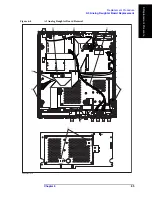
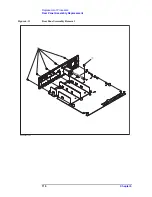
Refer to Figure 6-5 and for this procedure.
Step 1.
Remove the 3/4 rack module top as described in “3/4 Rack Module Top Replacement” on
page 90.
Step 2.
Remove the A3 Analog Daughter Board as described in “A3 Analog Daughter Board
Replacement” on page 94.
Step 3.
Disconnect the Mother-Analog Cable (item 1) from the A2 Analog Board.
Step 4.
Disconnect the Analog Source Cable (item 2) from the A2 Analog Board.
Step 5.
Remove the four 7 mm Standoff (item 3) from the A2 Analog Board.
Step 6.
Remove the TORX T20 screw (item 4) from the PCA E4980 USB. Then, Disconnect the
ground cable from the PCA E4980 USB.
Step 7.
Lift the A2 Analog Board and front panel toward upside.
Step 8.
Remove the five 5/8 inch nuts and washers (item 5) fastening the BNC connector.
Step 9.
Remove the A2 Analog Board from Front Panel.
Step 10.
Disconnect the two SMB cables (item 6) from the A2 Analog Board.
Replacement Procedure
Step 1.
Reverse the order of the removal procedure.
NOTE
When you fasten the A2 Analog Board with the five 5/8 inch nuts and washers, set box
torque wrench's torque to 17.4 in-lb.
When you fasten the A2 Analog Board with the four 7 mm Standoff, set box torque
wrench's torque to 8.7 in-lb.
Summary of Contents for E4980A
Page 12: ...12 Contents ...
Page 60: ...60 Chapter4 Troubleshooting Performance test failure troubleshooting ...
Page 86: ...86 Chapter5 Replaceable Parts Replaceable Parts List ...
Page 126: ...126 Chapter6 Replacement Procedure Display Interface Replacement ...
Page 136: ...136 AppendixB Firmware Update Update the E4980A firmware using USB cable ...
Page 140: ...140 AppendixC Power Requirement Power Requirements Figure C 3 Power Cable Supplied ...
Page 152: ...152 AppendixD Error Messages Error number 45 ...

