Chapter 5
109
Display Setting
Manual Scale Setting
5. Dis
play
Setting
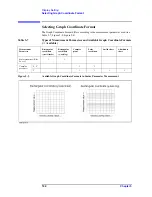
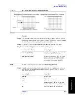
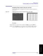
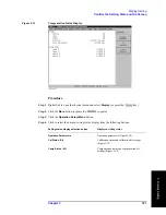
Figure 5-5
Scale setting according to the coordination format
Procedure
Step 1.
Click inside the window of the trace whose scale setting you want to adjust (or click the
measurement parameter name (area e.g.
2:
θ
z [
°
]
) in an overlay display) (or press the
key on the front panel), thus making the trace inside the window active.
Step 2.
Right-click to open the shortcut menu and select
Scale
(or press the
key).
Step 3.
Click the
Scale Entry
Button and select the scale setting format.
NOTE
When the y-axis is log scale, you cannot select
Scale Entry [Scale/Ref]
.
Step 4.
Using the numeric entry dialog box that appears by right-clicking inside each setting box
below (or using the
ENTRY/NAVIGATION
block keys on the front panel), enter the
value of each scale setting.
Scale Entry
Button Display
Scale setting format
Scale Entry [Scale/Ref]
Setting according to full-scale value, position of
reference line, value for reference line.
Scale Entry [Top/Bottom]
Setting according to max. and min. values (max.
and min. values can be changed by modifying
the reference line position while keeping the
corresponding full-scale value unchanged).
Scale Setting Box
Entry Value
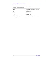
Full Scale
Full-scale value
Ref Val
Value for Y-axis reference line
Ref Pos
Position of reference line with the linear scale
showing 10 as max. value and 0 as min. value.
The value of the middle point on the Y-axis is 5.
Top
Max. value (highest value on y-axis scale)
Summary of Contents for E4991A
Page 6: ......
Page 24: ...18 Contents ...
Page 80: ...74 Chapter3 Setting Measurement Conditions Averaging Measurement Results ...
Page 220: ...214 Chapter9 Setup and Use of Control Management Functions System Recovery ...
Page 338: ...332 AppendixB Probe Station Connection Kit Option 010 OPEN SHORT LOAD Calibration ...
Page 428: ...422 AppendixD Menu References Menu References ...
Page 482: ...476 AppendixI Messages Wait measuring comp standard ...


