Chapter 6
161
Analysis of Measurement Results
Setting a Limit to the Trace and Making a Pass/Fail Determination
6.
Ana
lysis of
M
easur
em
ent
Result
s
Procedure
Step 1. Setting marker position and its upper limit and lower limit values
a.
Click inside the window of the trace on which you want to execute the marker limit test
(or click the measurement parameter name area, e.g.
2:
θ
z [
°
]
in the case of overlay
display) (or press
) to make the trace active.
b.
Right-click to open the shortcut menu and click
Marker Function
(or press
).
c.
Click the
More
button (or press
).
d.
Click the
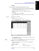
Limit Test Menu
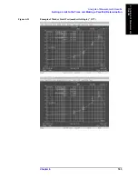
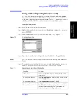
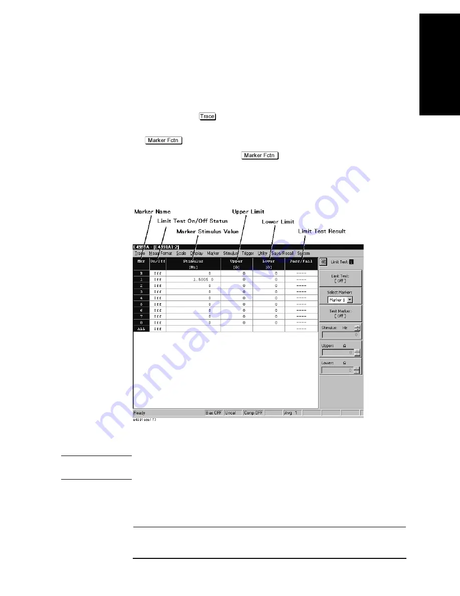
button to display the Limit Marker Test Setup Table (Figure
6-19).
Figure 6-19
Limit Marker Test Setup Table
e.
Use the
Select Marker
drop-down menu to select the marker to be used for limit setting
(
Marker R
,
Marker 1
to
Marker 8
).
NOTE
If you first select the marker, the
Test Marker
button automatically turns on. When the
Test
Marker
button is off, you should click this button to turn it on.
f.
For the markers selected in Step 1e. above, enter the values into the
Stimulus
box,
Upper
box, and
Lower
box.
Limit Marker Setting Box
Setting
Stimulus
Marker Position (stimulus value)
Summary of Contents for E4991A
Page 6: ......
Page 24: ...18 Contents ...
Page 80: ...74 Chapter3 Setting Measurement Conditions Averaging Measurement Results ...
Page 220: ...214 Chapter9 Setup and Use of Control Management Functions System Recovery ...
Page 338: ...332 AppendixB Probe Station Connection Kit Option 010 OPEN SHORT LOAD Calibration ...
Page 428: ...422 AppendixD Menu References Menu References ...
Page 482: ...476 AppendixI Messages Wait measuring comp standard ...

