background image

 256

Chapter 11


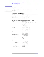
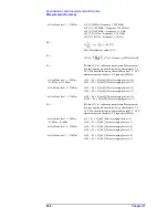
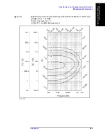
Specifications and Supplemental Information

Measurement Support Functions

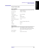
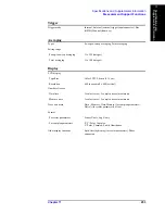
Internal reference signal output connector

High stability frequency reference output connector (option 1D5)

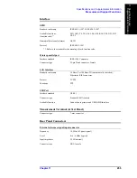
External trigger input connector

Figure 11-6 

Definition of Pulse Width (Tp)

Frequency

10 MHz (nominal)

Accuracy of frequency

Same as frequency accuracy described in “Frequency” on 
page 239

Level

+2 dBm (nominal)

Output impedance

50 

Ω

 (nominal)

Connector type

BNC, female

Frequency

10 MHz (nominal)

Accuracy of frequency

Same as frequency accuracy described in “Frequency” on 
page 239

Level

+2 dBm (nominal)

Output impedance

50 

Ω

 (nominal)

Connector type

BNC, female

Level

LOW threshold voltage: 0.5 V


HIGH threshold voltage: 2.1 V


Input level range: 0 to +5 V

Pulse width (Tp)

 2 

μ

sec (typical)


See Figure 11-6 for definition of Tp

Polarity

Positive or Negative (selective)

Connector type

BNC, female

Summary of Contents for E4991A

Page 1: ... highly sensitive microcircuits in your instrument ESD damage is most likely to occur as the test fixtures are being connected or disconnected Protect them from ESD damage by wearing a grounding strap that provides a high resistance path to ground Alternatively ground yourself to discharge any static charge built up by touching the outer shell of any grounded instrument chassis before touching the...

Page 2: ...of the instrument If you continue to operate without repairing the instrument there is a potential fire or shock hazard for the operator Instrument operates abnormally Instrument emits abnormal noise smell smoke or a spark like light during operation Instrument generates high temperature or electrical shock during operation Power cable plug or receptacle on instrument is damaged Foreign substance ...

Page 3: ...llerbescheinigung GER AUSCHEMISSION LpA 70 dB am Arbeitsplatz normaler Betrieb nach DIN 45635 T 19 Manufacturer s Declaration ACOUSTIC NOISE EMISSION LpA 70 dB operator position normal operation per ISO 7779 ...

Page 4: ...lowing applicable European Directives and carries the CE marking accordingly The Low Voltage Directive 73 23 EEC amended by 93 68 EEC The EMC Directive 89 336 EEC amended by 93 68 EEC To obtain Declaration of Conformity please contact your local Agilent Technologies sales office agent or distributor ...

Page 5: ...equipment is POLLUTION DEGREE 2 INDOOR USE product This equipment is tested with stand alone condition or with the combination with the accessories supplied by Agilent Technologies against the requirement of the standards described in the Declaration of Conformity If it is used as a system component compliance of related regulations and safety requirements are to be confirmed by the builder of the...

Page 6: ......

Page 7: ... Edition SERIAL NUMBERS This manual applies directly to instruments that have the firmware revision 2 1x and serial number prefix MY433 For additional important information about firmware revisions and serial numbers see Appendix A Manufacturing No E4991 90090 June 2012 ...

Page 8: ...4 2005 2006 2012 Agilent Technologies Manual Printing History The manual s printing date and part number indicate its current edition The printing date changes when a new edition is printed minor corrections and updates that are incorporated at reprint do not cause the date to change The manual part number changes when extensive technical changes are incorporated March 2001 Preliminary part number...

Page 9: ...Away from Live Circuits Operators must not remove instrument covers Component replacement and internal adjustments must be made by qualified maintenance personnel Do not replace components with the power cable connected Under certain conditions dangerous voltage levels may remain even after the power cable has been disconnected To avoid injuries always disconnect the power and discharge circuits b...

Page 10: ...injury or death to personnel CAUTION This Caution sign denotes a hazard It calls attention to a procedure practice or condition that if not correctly performed or adhered to could result in damage to or destruction of part or all of the instrument NOTE This Note sign denotes important information It calls attention to a procedure practice or condition that is essential for the user to understand C...

Page 11: ...re and firmware designated by Agilent Technologies for use with an instrument will execute its programming instruction when properly installed on that instrument Agilent Technologies does not warrant that the operation of the instrument or software or firmware will be uninterrupted or error free Limitation of Warranty The foregoing warranty shall not apply to defects resulting from improper or ina...

Page 12: ...d or emphasis Sample Italic Italic type is used for emphasis key Indicates a hardkey key on the front panel or external keyboard labeled Sample key may be omitted Sample menu button box Indicates a menu button box on the screen labeled Sample which can be selected executed by clicking menu button or box may be omitted Sample block toolbar Indicates a block group of hardkeys or a toolbar setup tool...

Page 13: ...alysis Refer to this manual when you use the E4991A for the first time Programming Manual Part Number E4991 900x2 attached to Option ABA This manual provides programming information for performing automatic measurement with the E4991A It includes an outline of remote control procedures for detecting measurement start trigger and end sweep end application programming examples a command reference an...

Page 14: ...y PCs as doing so may cause malfunctions Also note the followings Do not update the Windows operating system installed in this machine to the Windows operating system for ordinary PCs Doing so will cause malfunctions Do not allow any computer virus to infect the system This machine has no virus check function nor anti virus software installed Agilent Technologies will not be held liable for any fa...

Page 15: ...rnal monitor output terminal VIDEO 29 6 GPIB connector 29 7 High stability frequency reference output connector Ref Oven Option 1D5 only 29 8 External reference signal input terminal Ext Ref In 10 MHz 0 dBm 30 9 Internal reference signal output connector Int Ref Out 30 10 Unused ports Reserved 30 11 Rear USB port 30 12 Mini DIN mouse port MOUSE 30 13 Mini Din keyboard port KYBD 31 14 Serial number...

Page 16: ...electing Trigger Target Trigger Event 62 Procedure 62 Single Sweep Continuous Sweep and Sweep Stop 63 Procedure 63 Selecting Polarity of External Trigger Input Signal 64 Procedure 64 CW Frequency Setting 65 Procedure 65 Sweeping a Plural Number of Sweep Areas under Different Conditions at One Time Segment Sweep 66 Procedure 67 Averaging Measurement Results 71 Averaging Plural Sweeps Sweep to Sweep...

Page 17: ...ement 102 Procedure 102 Selecting Graph Coordinate Format 104 Procedure 105 Autoscale Adjustment 107 Autoscale Adjustment for each Trace 107 Autoscale Adjustment for all Traces at Once 107 Manual Scale Setting 108 Scale Setting in Rectangular Coordinates 108 Scale Setting on Complex Plane 111 Scale Setting in Polar Coordinate Format 112 Setting of Reference Line Value by Using Marker 112 Zooming a...

Page 18: ...cting Marker Analysis Target Trace Data Memory 139 Procedure 139 Search for Max and Min Measurement Value 140 Procedure 140 Search for Target Point of Measurement Value 142 Procedure 142 Peak Search 144 Maximal Point and Minimal Point 144 Positive Peak and Negative Peak 145 Outline of Peak Search Function 146 Procedure 146 Define the Peaks Using Marker 148 Working Out Trace Average Standard Deviat...

Page 19: ... display information 183 Recalling Saved Image File 184 8 Printing Measurement Results and Internal Data Printing Measurement Graphs and Internal Data Lists 186 Supported Printers 187 How to print data on the screen 187 Installing Printer Drivers 191 How to install a printer driver 191 9 Setup and Use of Control Management Functions Setting the GPIB 194 Setting talker listener GPIB address of E499...

Page 20: ...on Definitions 238 Measurement Parameters and Range 238 Measurement Parameters 238 Measurement Range 238 Source Characteristics 239 Frequency 239 Oscillator Level 239 Output Impedance 240 DC Bias Option 001 241 DC Voltage Bias 241 DC Current Bias 241 DC Bias Monitor 241 Probe Station Connection Kit Option 010 242 Oscillator Level 242 Sweep Characteristics 243 Sweep Conditions 243 Segment Sweep 243...

Page 21: ...ion 002 and 007 285 Measurement Parameter 285 Typical Effects of Temperature Change on Permittivity Measurement Accuracy 298 A Manual Changes Manual Changes 308 Change 6 309 Change 5 309 Change 4 312 Change 3 314 Change 2 316 Change 1 318 B Probe Station Connection Kit Option 010 Option 010 Overview 322 Recommended Probe Stations 323 Recommended Probe Heads 323 Mounting Test Head and Connecting Ca...

Page 22: ...8 Meas Format Menu 379 Scale Menu 380 Display Menu 384 Marker Menu 389 Stimulus Menu 397 Trigger Menu 409 Utility Menu 411 Save Recall Menu 416 System Menu 418 E Theory on Material Measurement Dielectric Material Measurement 424 Definition of Permittivity 424 Measurement Principle of Dielectric Material 425 Error Components of 16453A Test Fixture 426 Magnetic Material Measurement 428 Definition of...

Page 23: ...t test 453 Function Comparison List 454 I Messages Alphabetical Order 462 A 462 B 462 C 462 D 464 E 464 F 465 G 465 I 465 M 467 N 467 O 469 P 469 Q 470 R 471 S 471 T 472 U 473 Messages indicating the internal status of the equipment 474 Messages indicating measurement failure 474 Messages indicating the results or current status of processing 475 ...

Page 24: ...18 Contents ...

Page 25: ...19 1 How to Use This Operation Manual 1 How to Use This Operation Manual This chapter explains how to most efficiently use this Operation Manual ...

Page 26: ...tions for Dielectric Measurement Chapter 5 Basic Operations for Magnetic Measurement Operation Manual this book Chapter 2 Function Overview on page 21 3 Performing measurements manual operation Operation Manual this book Chapter 3 Setting Measurement Conditions on page 41 Chapter 4 Calibration and Compensation on page 75 Chapter 5 Display Setting on page 95 Appendix B Probe Station Connection Kit ...

Page 27: ... 2 Function Overview 2 Function Overview This chapter describes the functions of the Agilent E4991A Impedance Material Analyzer available to the user from the front panel rear panel and LCD display blocks ...

Page 28: ...ont Panel Blocks The names and functions of the E4991A front panel blocks are shown below Figure 2 1 E4991A front panel 1 Standby switch 2 3 5 built in floppy disk drive 3 Color LCD display 4 Measurement block 5 Stimulus block 6 Entry navigation block 7 System block 8 Utility 9 Test head interface ...

Page 29: ...ettings measured data calibration compensation data image data displayed on the LCD display VBA Visual Basic for Applications programs and other data to a floppy disk or to recall them It works with 3 5 inch 1 44 MB DOS formatted floppy disks The floppy disk access lamp is located to the left of the disk slot It lights up in green when the floppy disk drive accesses the disk by either read or writ...

Page 30: ...ng with this toolbar you can set the general settings of the view on the display except for the vertical axis form of a measurement graph and scale settings key Used to show the Marker toolbar at the right of the display By working with this toolbar you can set the basic settings of the marker which is a small inverted delta symbol By using the marker various measurement trace parameters can be re...

Page 31: ... move the onscreen setting cursor up down left or right key click key By pressing this key you can select and execute the feature that the cursor is placed over It has the same function as pressing the rotary knob key numeric keys Used to type numeric values one by one in the cursor position By pressing a unit key after entering a value the value and unit are set and executed key When you press th...

Page 32: ... key can be used instead of pressing the Cancel or x button in a dialog box key When you press this key when a dialog box is onscreen the entered setting is executed and the box closes This key can also be used instead of pressing the OK button in a dialog box key By pressing this key the leftmost menu opens in the menu bar at the top of the display Then the arrow keys can be used to move the curs...

Page 33: ... current to the DUT port Doing this could cause operational failure Pay particular attention to whether the capacitor has been charged Fully discharge the device under test before connecting it to the test head DUT port or test fixture CAUTION Whenever you connect a DUT to or disconnect it from the DUT port for measurement you must first turn off the dc bias or set the sweep to the hold state in s...

Page 34: ...apter2 Function Overview Names and Functions of Rear Panel Blocks Names and Functions of Rear Panel Blocks The names and functions of the E4991A rear panel blocks are shown below Figure 2 3 E4991A Rear Panel ...

Page 35: ... trigger input connector Ext Trig Connector type BNC connector female This is the terminal through which a trigger signal is input to begin execution of measurement It detects a trigger by the rising or falling edge following the Low or High level of a TTL compatible signal To trigger measurement with a signal input to this terminal you must set the trigger source to EXTERNAL external trigger inpu...

Page 36: ...nector Ref Oven Option 1D5 only to the option by using the included BNC m BNC m cable 9 Internal reference signal output connector Int Ref Out Connector type BNC connector male This is an output terminal for the E4991A internal reference signal By connecting this terminal and the external reference signal input terminal of other equipment it can be used by phase locking it with the E4991A referenc...

Page 37: ...is port is used to connect a Mini DIN style keyboard Because alphabetic characters and symbols directed to the E4991A can be input only through a keyboard you will need it for such tasks as editing a VBA program or typing a file name The arrow and numeric keys on the keyboard operate in the same manner as those on the E4991A front panel Thus you can use the keyboard for cursor navigation instead o...

Page 38: ...useful when printing and saving the onscreen measurement results 2 Menu bar You can make most settings for the E4991A by working with this menu bar in any or all of the following ways o Using the mouse connected to the E4991A click a menu name on the menu bar In the menu that appears select the desired menu item by clicking with the mouse o Press the key in the 6 Entry navigation block ENTRY NAVIG...

Page 39: ...to the E4991A type the alphabetic character underlined in the desired menu name to open the menu In the menu that appears select the desired menu item by typing the underlined character in the same manner You do not need to press the key after making a selection in this way Once a menu opens you can use the following operations instead of the above First use the appropriate arrow keys on the keybo...

Page 40: ...xt menu on the right Disabled Press Disabled Press Move the pointer to the desired menu name on the menu bar Move the cursor up in a menu Disabled Press Disabled Press or an alphabetic character key 1 2 Move the pointer to the desired menu name on the menu bar Move the cursor down in a menu Disabled Press Disabled Press or an alphabetic character key 1 2 Move the pointer to the desired menu name o...

Page 41: ...S on page 24 except for Keys in 7 System block SYSTEM on page 26 except for o Work with the 2 Menu bar on page 32 to show the setup toolbar associated with a menu item o Right click to open the shortcut menu Figure 2 5 and click the desired setup toolbar name Figure 2 5 Shortcut menu You can also bring up the marker shortcut menu Figure 2 6 by right clicking a marker on the display Figure 2 6 Mark...

Page 42: ...nd execution To move the cursor over the blocks in a toolbar use the keys o Move the cursor down to the desired block in a toolbar by pressing or move the cursor up by holding down and pressing on the keyboard connected to the E4991A Then press the key for selection and execution To open a drop down list box hold down while pressing and then choose an item from the drop down list box by releasing ...

Page 43: ...led Disabled Press Press Right click the entry box to open the numeric entry dialog box and click the desired buttons Execute numeric data entry with the unit added Disabled Disabled Press or executed Type the unit and press executed Right click the entry box to open the numeric entry dialog box and click the desired buttons Increase Decrease the entered numeric values Press and turn clockwise or ...

Page 44: ... 4 Measurement block MEASUREMENT on page 23 6 Trace 2 This is one of the traces that can be displayed simultaneously on the E4991A The bar indicating the trace and scale colors of Trace 2 as well as the measurement parameter names and their units in this example θz are displayed in the upper middle area 7 Markers These are used to read the values on a trace as numeric values The value at each mark...

Page 45: ...length of the test fixture xxx represents the currently entered electrical length value in meters For example Del 10m indicates that the fixture s electrical length is set to 10 millimeters Avg xx The point averaging factor is set to xx Hold The trigger is on hold Manual Waiting for manual trigger External Waiting for external trigger GPIB Bus Waiting for GPIB trigger trigger command ExtRef The 8 ...

Page 46: ...Functions of LCD Display Areas Ovld An overload occurred in the measurement circuit One or more measurement values are invalid This indicator goes on when the device under test is removed or installed during measurement Indicator Description ...

Page 47: ...ting Measurement Conditions 3 Setting Measurement Conditions This chapter describes the method used to set up the measurement conditions test signal and sweep for the Agilent E4991A impedance material analyzer ...

Page 48: ...ate It is always possible to return the E4991A to its preset state by taking one of the following actions Right click to open the shortcut menu and click Preset Execute Click System Preset from the menu bar Press in the SYSTEM block on the front panel For more details on the E4991A s initial settings including the preset state refer to Chapter G Initial Settings on page 439 ...

Page 49: ...measurement type Step 2 Enter material dimensions Using the numeric entry dialog box that appears by right clicking inside the setting box described below or using the ENTRY NAVIGATION block key of the front panel enter the necessary material dimensions Material Type Box Material Measurement Type Impedance Impedance measurement measurement of general impedance parameters except for permittivity an...

Page 50: ...ter3 Setting Measurement Conditions Setting Material Measurement Parameter Option 002 only Figure 3 1 Material shape parameter for dielectric material Figure 3 2 Material shape parameter for magnetic material ...

Page 51: ...a it will change from to Right click to open the shortcut menu and click Trace Scaler or Trace Complex indicates trace number Click Trace Scaler or Trace Complex indicates trace number from the menu bar Press in the MEASUREMENT block on the front panel each press changes the active trace in sequential order Identifying Active Trace The selected active trace can be identified in the following ways ...

Page 52: ...NOTE Option 001 must be installed to sweep by dc bias voltage or current Procedure Step 1 Right click to open the shortcut menu and click Sweep Setup or press Step 2 Click and open the Sweep Parameter box and click to select the sweep parameter Sweep Parameter box Sweep Parameter Frequency Frequency Power Source power level Bias Voltage dc bias voltage option 001 only Bias Current dc bias current ...

Page 53: ...ing the numeric entry dialog box by right clicking inside the Span box or using the ENTRY NAVIGATION block keys on the front panel enter zero as the sweep span value Step 2 Set sweep time a Right click to open the shortcut menu and click Sweep Setup or press b Click the Sweep Time button c Using the numeric entry dialog box by right clicking inside the Sweep Time box or using the ENTRY NAVIGATION ...

Page 54: ...ected as a sweep parameter the sweep type is fixed to linear sweep and cannot be changed For more details on selecting the sweep parameter see Selecting Sweep Parameter on page 46 If the segment sweep table has not been prepared the segment sweep cannot be selected when the segment sweep table has been not prepared the Segment is not displayed even if the Sweep Type box is opened For more details ...

Page 55: ...e sweep direction You can select the sweep direction by following the procedure below Procedure Step 1 Right click to open the shortcut menu and click Sweep Setup or press Step 2 Click the Sweep Direction button and select the Sweep Direction Sweep Direction Button Sweep Direction Setup Sweep Direction Up Upward in the direction from sweep start value to sweep stop value Sweep Direction Down Downw...

Page 56: ...d after a signal is applied to a DUT but before actual measurement starts point delay This function is useful for example when a certain period is required before the characteristics of the DUT can become stable after a signal is applied Another application of this function is to observe the changes in a DUT s impedance over time for a long span Figure 3 3 shows the definitions of sweep time sweep...

Page 57: ... delays at a measurement point Point Delay When the measurement point delay time Point Delay segment delay time Segment Delay or sweep delay time Sweep Delay is changed the sweep time Sweep Time setting is automatically changed NOTE Segment delay time is only effective when the sweep type is set to segment sweep For details on segment sweep refer to Sweeping a Plural Number of Sweep Areas under Di...

Page 58: ...ng to Center Span values change the values in the Center box and Span box in tool bar You can use any of the following methods to change the value in the box Right click in the box and enter the set value by clicking the numerical and unit buttons that appear Click the up or down s or t button to increase or decease the sweep area setting value After all character strings in a box have been select...

Page 59: ...tart box and finish the entry by pressing NOTE If you enter the sweep start and sweep stop values the sweep center and sweep span values will be automatically calculated based on those values and displayed in their respective boxes On the other hand if you enter the sweep center and sweep span values the sweep start and sweep stop values will be automatically calculated based on the entered sweep ...

Page 60: ...e position of the active marker on a trace stimulus value in the same way as setting sweep start value sweep stop value or sweep center value It is also possible to assign the distance between Marker R and Marker 1 or 2 8 which is the difference between stimulus values in the same way as setting sweep span value Figure 3 5 ...

Page 61: ...Chapter 3 55 Setting Measurement Conditions Setting Sweep Area with Marker 3 Setting Measurement Conditions Figure 3 5 Sweep Area Setting with the Marker ...

Page 62: ... values NOTE After the sweep area is changed no trace is displayed in the new sweep area until a new measurement is taken Button Assigning Marker Value Sweep Area Display Mode Start Assign the stimulus value of the active marker as the sweep start value As a result the position of the marker establishes a new sweep start point Stop Assign the stimulus value of the active marker as the sweep stop v...

Page 63: ...ss Step 2 Using the numeric entry dialog box that appears by right clicking inside the Number Of Points box or using the ENTRY NAVIGATION block keys on the front panel enter the number of points NOTE Number of points can be set as an integer from 2 to 801 Number of points is set by the segment sweep table when the sweep type is segment segment sweep For setting the segment sweep table see Sweeping...

Page 64: ...nected to the measurement terminal Pset P50 Voltage V Voltage value Vset is twice the value of V50 when the measurement terminal is connected to the 50 Ω resistor Vset V50 2 This value is approximately equal to the voltage when the measurement terminal is open 1 Current A Current value Iset is twice the value of I50 when the measurement terminal is connected to the 50 Ω resistor Iset I50 2 This va...

Page 65: ...it that you set is used for sweeping the oscillator level and also for setting the fixed oscillator level which is used for sweeping any parameter other than oscillator level Step 2 Oscillator Level Setting Using the numeric entry dialog box that appears by right clicking inside the Osc Level box or using the ENTRY NAVIGATION block keys on the front panel enter the Osc level For example use the EN...

Page 66: ...cking inside the Bias Limit box or the ENTRY NAVIGATION block keys on the front panel to enter the dc Bias Limit value Step 4 Apply dc Bias a Click the dc Bias button and turn the dc Bias on If this operation is made during a sweep measurement the sweep mode will automatically stop the sweep dc Bias will not be applied after the sweep is stopped b Execute sweep measurement according to the operati...

Page 67: ...pter 11 Specifications and Supplemental Information on page 237 For more details on using GPIB see Programming Manual Trigger Source Box Trigger Source Internal Internal continuous trigger generated automatically by the E4991A Manual Manual trigger generated by clicking the Manual Trigger button on the Trigger Setup toolbar or by pressing 1 1 The manual trigger can also be executed by clicking Tri...

Page 68: ... page 61 Procedure Step 1 Right click to open the shortcut menu and click Trigger Setup or press Step 2 Click and open the Trigger Event Box and click to select the desired Trigger Event NOTE It is necessary to prepare a segment sweep table before using a segment trigger For more details on preparing a segment sweep table see Sweeping a Plural Number of Sweep Areas under Different Conditions at On...

Page 69: ...e by clicking one of the three buttons for sweep mode selection NOTE A check mark to the left of the sweep mode selection button indicates the mode that is currently selected and executed Sweep Mode Selection button Sweep Mode Hold Sweep stop sweep is immediately stopped and not restarted even if a trigger is generated Single Single sweep single sweep is triggered and when the sweep finishes Sweep...

Page 70: ... connector on the rear panel by following the procedure below Procedure Step 1 Right click to open the shortcut menu and click Trigger Setup or press Step 2 Click the Trigger Polarity Button and select the external trigger signal polarity Trigger Polarity Button External Trigger Signal Polarity Positive Positive polarity detects increasing TTL signal and triggers Negative Negative polarity detects...

Page 71: ... to set CW frequency In order to set CW frequency you should preset the sweep parameter to one other than frequency according to Selecting Sweep Parameter on page 46 Procedure Step 1 Right click to open the shortcut menu and click Source or press Step 2 Using the numeric entry dialog box that appears by right clicking inside the CW Freq box or using the ENTRY NAVIGATION block keys on the front pan...

Page 72: ...ase certain measurement conditions i e number of points point averaging factor source unit oscillator level DC bias mode level limit can be set for each segment and the entire series of such segment setups can be sequentially executed as a single sweep Figure 3 6 By using this feature it is possible to take a sweep measurement in only the desired area and to skip the frequency areas that you do no...

Page 73: ...gment Sweep Table The default values for the first segment are listed in the columns of Chapter G Initial Settings on page 439 When the table already has segments the last segment in the table is copied to create a new segment d Edit the added segment using the following buttons and boxes Segment Sweep Setting Button Box Setting Function Start spin box This sets sweep start frequency of segment St...

Page 74: ...spin box and edit the segment in accordance with step d NOTE You can directly call up the setup box for changing an item s value by clicking the current value in the segment table on the screen Figure 3 7 More button This opens the toolbar showing the buttons described below button This returns to the toolbar showing the buttons described above Osc Level spin box This sets source level of segment ...

Page 75: ...isplay button and select the appropriate setting for the graph s horizontal axis by referring to the table below See Figure 3 9 Segment Display Button Graphic Horizontal Axis Display Segment Display Order Base Order base defines the horizontal axis at equal intervals in order of measurement Segment Display Freq Base Frequency base defines the horizontal axis as a linear frequency axis with the min...

Page 76: ...70 Chapter3 Setting Measurement Conditions Sweeping a Plural Number of Sweep Areas under Different Conditions at One Time Segment Sweep Figure 3 9 Order Base Display and Frequency Base Display ...

Page 77: ...Measurement value from n times sweeping at the measurement point vector quantity F Sweep to sweep averaging n times Set the sweep to sweep averaging by following the procedure below Procedure Step 1 Right click to open the shortcut menu and click Meas Format or press Step 2 Click the Sweep Average button to turn the sweep to sweep averaging on Step 3 Enter the number of times for sweep to sweep av...

Page 78: ...veraging Measurement Results NOTE You may set the number of times for sweep to sweep averaging in integers from 1 to 999 If you click the Sweep Average Restart button while performing sweep to sweep averaging n in Equation 3 1 will be reset to 1 ...

Page 79: ...ment point vector quantity Sn Measurement value from n times sweeping at the measurement point vector quantity F Point averaging n times Set point averaging by following the procedure below Procedure Step 1 Right click to open the shortcut menu and click Sweep Setup or press Step 2 Enter the number of times for point averaging with the numeric entry dialog box that appears by right clicking inside...

Page 80: ...74 Chapter3 Setting Measurement Conditions Averaging Measurement Results ...

Page 81: ...75 4 Calibration and Compensation 4 Calibration and Compensation It is necessary to perform calibration and compensation before using the Agilent E4991A to take measurements ...

Page 82: ...ompleting the open short load calibration This can only be executed when the 7 mm connector is used as the calibration reference plane This decreases high Q low loss coefficient above the frequency band near 1 GHz which is difficult to decrease by only using open short load calibration Port extension compensation 1 When the port is extended from the compensation reference plane by a coaxial cable ...

Page 83: ...eference plane The most common calibration reference plane is the 7 mm terminal plane in front of the test head In this case you may use open short load and low loss capacitor standards included in the calibration kit supplied with the E4991A You may also use the terminal plane as a calibration reference plane for connecting the tested device However you need to use a calibration standard working ...

Page 84: ... Connect the coaxial terminal calibration kit to the coaxial terminal of the test head calibration reference plane 2 Calibration of low loss capacitor This calibration is only used for such cases as high Q measurement when high accuracy or consideration of low loss factor is required at a frequency above approx 1 GHz Connect the low loss capacitor to the calibration reference plane 2 3 Compensatio...

Page 85: ...e number of sweep measurement points NOP The most accurate DUT measurement can be performed Need to retake the calibration compensation data if measurement points frequency and or power are changed Fixed frequency Fixed power point mode Fixed Freq Pwr 372 Preset points Table 4 4 372 Preset points Table 4 5 372 3 1116 points Not necessary to retake the calibration compensation data even if the meas...

Page 86: ... GHz 1 05 GHz 1 06 GHz 1 07 GHz 1 08 GHz 1 09 GHz 1 10 GHz 1 11 GHz 1 12 GHz 1 13 GHz 1 14 GHz 1 15 GHz 1 16 GHz 1 17 GHz 1 18 GHz 1 19 GHz 1 20 GHz 1 21 GHz 1 22 GHz 1 23 GHz 1 24 GHz 1 25 GHz 1 26 GHz 1 27 GHz 1 28 GHz 1 29 GHz 1 30 GHz 1 31 GHz 1 32 GHz 1 33 GHz 1 34 GHz 1 35 GHz 1 36 GHz 1 37 GHz 1 38 GHz 1 39 GHz 1 40 GHz 1 41 GHz 1 42 GHz 1 43 GHz 1 44 GHz 1 45 GHz 1 46 GHz 1 47 GHz 1 48 GHz...

Page 87: ...ged as needed For more on this procedure see Definition of Calibration Compensation Kit on page 91 Step 2 Open short load low loss capacitor calibration Measure calibration data of open short load with the 7 mm terminal of the test head To measure a device with high Q low loss factor at a frequency higher than approx 1 GHz calibration of low loss capacitor needs to be done For more on this procedu...

Page 88: ...ation and Compensation Using 7 mm Test Port as a Calibration Reference Plane Step 5 Open short compensation Measure the compensation data of open short according to the test fixture used For more on this procedure see Fixture Compensation on page 89 ...

Page 89: ... following procedure Step 1 Definition of calibration kit The definition of the calibration kit used should be changed as needed For more on this procedure see Definition of Calibration Compensation Kit on page 91 Step 2 Connection of test fixture Connect a test fixture in front of the 7 mm terminal For more on the connecting method see the fixture s operation manual Step 3 Open short load calibra...

Page 90: ...epeatability of later measurements b Click the Meas Open button and measure the open calibration data NOTE When you want to interrupt measurement of calibration data click the Abort Cal Meas button shown during measurement When the measurement of each type of calibration data is finished a check mark will appear to the left side of the corresponding calibration execution button This mark indicates...

Page 91: ...ibration reference plane Step 6 Finishing calibration data measurement and confirmation of calibration state a Click the Done button to finish measuring the calibration data NOTE To delete all measured calibration data click the Cal Reset button At the same time all stored fixture compensation data are also deleted b Confirm the calibration state according to the display of the Cal Menu button as ...

Page 92: ...on line as a distributed parameter circuit without loss Usually port extension compensation is not necessary because the test fixture is connected directly to the front of 7 mm terminal of the test head Procedure Step 1 Right click to open the shortcut menu and click the Cal Comp button or press Step 2 By using the numeric entry dialog box that appears by right clicking inside the Port Extension b...

Page 93: ...cal value NOTE The 16453A is automatically selected when the permittivity measurement Permittivity is selected as material type Material Type The 16454A fixture size S or 16454A fixture size L can be selected when the permeability measurement Permeability is selected as material type Material Type For selecting the material type refer to Setting Material Measurement Parameter Option 002 only on pa...

Page 94: ... fixture If User is selected in step 1 b enter the electrical length of the fixture to be used by using the numeric entry dialog box that appears by right clicking inside the Fixture Length box or using the ENTRY NAVIGATION block keys on the front panel Fixture Type box Test Fixture None Electrical length compensation off 16191A 16191A 16192A 16192A 16193A 16193A 16194A 16194A 16196A 16196A 16196B...

Page 95: ... button that appears during compensation data measurement When the measurement of each type of calibration data is finished a check mark will appear to the left side of the corresponding calibration execution button This mark indicates that the calibration data is stored Step 4 Measurement of short compensation data Short compensation is executed according to the following procedure if you do not ...

Page 96: ... 3 Click the Comp Open button and Comp Short button to toggle their states On Off NOTE When either open compensation or short compensation should be on the Comp Menu button is displayed as On see step 5 Note in Measuring Fixture Compensation Data on page 89 If you click the Done button all stored compensation data will be automatically turned on Display of Comp Open Button State of Open Compensati...

Page 97: ...tcut menu and click the Cal Comp button or press Step 2 Click the Cal Kit Menu button Step 3 Click and open the Cal Kit Type box and click to select User NOTE If you select 7 mm the definition prepared in advance is automatically applied you cannot change the definition If you use the 7 mm calibration kit supplied with the E4991A please select 7 mm Step 4 By using the numeric entry dialog box that...

Page 98: ...ont panel enter the definition of the compensation kit Definition of Compensation Kit Figure 4 5 shows the circuit model of the compensation kit adopted in the E4991A Calibration Kit Definition Box Value to be defined Open G S Equivalent parallel conductance G of Open calibration standard preset state 0 S Open C F Equivalent parallel capacitance C of Open Calibration standard preset state 82 fF Sh...

Page 99: ...icking inside the compensation kit definition box or using the ENTRY NAVIGATION block keys on the front panel enter the definition of the compensation kit Calibration Kit Definition Box Value to be defined Open G S Equivalent parallel conductance G of Open compensation standard preset state 0 S Open C F Equivalent parallel capacitance C of Open Compensation standard preset state 0 F Short R Ω Equi...

Page 100: ...n coefficient arrays fixture compensation data arrays and fixture compensation coefficient arrays Figure 7 1 on page 168 For more information on restoring settings refer to Initial Settings Settings that can be Saved Recalled Settings that can be Backed Up on page 440 Procedure Step 1 Right click to open the shortcut menu and then click Cal Comp or press Step 2 Click the Recover Cal Comp State but...

Page 101: ...95 5 Display Setting 5 Display Setting This chapter describes the various ways of displaying the measurement results of the Agilent E4991A RF Impedance Material Analyzer ...

Page 102: ...the Number of Traces drop down box and select the desired types and numbers of traces to display Number of Traces Box Types and Numbers of Displayed Traces 1 Scalar Scalar trace 1 2 Scalar Scalar trace 2 3 Scalar Scalar trace 3 1 Complex Complex traces 1 2 Complex Complex traces 2 1 Sclr 1 Cmplx Scalar trace 1 Complex traces 1 1 Sclr 2 Cmplx Scalar trace 1 Complex traces 2 2 Sclr 1 Cmplx Scalar tr...

Page 103: ...ces 5 Display Setting Figure 5 1 Display of 3 Scalar Traces 2 Complex Traces 3 Sclr 2 Cmplx NOTE In Figure 5 1 scalar traces are displayed in the split display mode For details about overlay and split displays refer to Overlay Display and Split Display of Graphs on page 114 ...

Page 104: ...Maximize a Display Window on the Screen When multiple windows are displayed on the screen after selecting the number of traces to display the window that contains the active trace can be maximized on the screen Figure 5 2 Figure 5 2 Maximize and Restore a Display Window ...

Page 105: ...ze or press to make the window active The frame of the selected window becomes red Step 2 Right click to open the shortcut menu and then select Display or press Step 3 Click More or press Step 4 Click Window Maximize to maximize the window To go back to the original window size and configuration of windows showing all traces click Window Restore ...

Page 106: ...olute value of admittance θy Phase of admittance G Equivalent parallel conductance B Equivalent parallel susceptance Γ Reflection parameter θγ Phase of reflection parameter Γx Real part of reflection coefficient complex number Γy Imaginary part of reflection coefficient complex number Cp Equivalent parallel capacitance Cs Equivalent series capacitance Lp Equivalent parallel inductance Ls Equivalen...

Page 107: ...tcut menu and select Meas Format or press the key on the front panel Step 3 Click on the Meas Parameter drop down box and select the desired Meas Parameter Table 5 2 Table 5 1 NOTE When using the E4991A with option 002 material measurement function it is possible to select dielectric material or magnetic material measurement parameters in addition to the measurement parameters listed above See Set...

Page 108: ...box and select the desired measurement parameter In material measurement parameters in Table 5 3 to Table 5 6 are added to the impedance measurement parameters Table 5 3 Meas Parameter Box for dielectric material scalar traces Meas Parameter Measurement Parameter εr Real part of complex permittivity εr Imaginary part of complex permittivity tanδ ε Dielectric loss tangent εr Absolute value of compl...

Page 109: ... Display Setting Setting Measurement Parameter Material Measurement 5 Display Setting Table 5 6 Meas Parameter Box for Magnetic Material Complex Trace Meas Parameter Measurement Parameter μr Complex permeability μr ...

Page 110: ...gure 5 3 Figure 5 4 Figure 5 3 Available Graph Coordinate Formats in Scalar Parameter Measurement Table 5 7 Types of Measurement Parameters and Available Graph Coordinate Formats Available Measurement Parameter Rectangular coordinate y axis linear Rectangular coordinate y axis log Complex plane Polar coordinate Smith chart Admittance chart Scalar parameter Z θz Ls etc Complex parameter Z Y Γ ...

Page 111: ...in an overlay display or press the key on the front panel thus making the trace active Step 2 Click and open the shortcut menu and select Meas Format or press the key Step 3 Click on the Format drop down box and select the desired coordinate format Format Box for scalar parameter measurement Coordinate Format Lin Y Axis Rectangular coordinates of Y axis linear X axis Sweep parameter Y axis Measure...

Page 112: ...mplex parameter measurement Coordination Format Complex Complex plane X axis Actual number Y axis imaginary number Polar Polar coordinate Smith 1 Smith chart Admittance 1 Admittance chart 1 Selection is only possible when the measurement parameter is Γ complex reflection parameter ...

Page 113: ...2 θz in an overlay display or press the key on the front panel thus making the trace active Step 2 Right click to open the shortcut menu and select Scale or press the key Step 3 Click the Autoscale button to execute Autoscale Adjustment Autoscale Adjustment for all Traces at Once Procedure Step 1 Right click to open the shortcut menu and select Scale or press the key Step 2 Click the Autoscale All...

Page 114: ...e Bottom Table 5 8 Method of setting scale for each coordination format Measurement parameter Coordinate format to select Method of manually setting scale Scalar parameter Z θz Ls etc Rectangular coordinates Y axis linear Setting according to full scale value Full Scale position of reference line Ref Pos and value of reference line Ref Val Setting according to max value Top and min value Bottom Re...

Page 115: ...meric entry dialog box that appears by right clicking inside each setting box below or using the ENTRY NAVIGATION block keys on the front panel enter the value of each scale setting Scale Entry Button Display Scale setting format Scale Entry Scale Ref Setting according to full scale value position of reference line value for reference line Scale Entry Top Bottom Setting according to max and min va...

Page 116: ...with the Reference Line button Instead of entering the value of the reference line as a numerical value into the Ref Val box you can directly enter the position of the marker measurement value into the reference line value See Setting of Reference Line Value by Using Marker on page 112 Bottom Min value lowest value on y axis scale Scale Setting Box Entry Value ...

Page 117: ...p 3 Using the numeric entry dialog box that appears by right clicking inside each Scale Setting Box or using the ENTRY NAVIGATION block keys on the front panel enter each value NOTE Instead of entering the value of the reference line as a numerical value into the Ref X box and Ref Y box you can directly enter the actual number portion and imaginary number portion of the marker position s measureme...

Page 118: ...alue can be set by using the position of marker when the coordinate format is rectangular Y axis linear or a complex plane Step 1 Click inside the window of the trace whose scale you want to set or click the measurement parameter name area e g 2 θz in overlay display or press the key to make the trace active Step 2 Move the marker to the position on the trace that you want to use as the value of t...

Page 119: ... the diagonal line of the imaginary rectangular area while holding down the mouse button Step 3 Release the left mouse button when the cursor reaches to the opposite corner of the rectangle from where you started NOTE To return the zoomed trace to the original size simply click the cursor once in the display It is not possible to continue zooming the trace more than once The trace cannot be zoomed...

Page 120: ... display left and split display right of graphs Procedure Step 1 Right click to open the shortcut menu and select Display or press the key Step 2 Click the Display Scalar Trace button to toggle between Overlay and Split NOTE Complex traces are always viewed in split display and never in overlay display Display Scalar Trace Button Overlay Split Display Display Scalar Trace Overlay Overlay display D...

Page 121: ...red values can be displayed in a numerical list Figure 5 10 Displaying the measured values in list Off left and On right Procedure Step 1 Right click to open the shortcut menu and select Display or press the key Step 2 Click the List Values button to toggle display of list values On and Off If multiple traces are displayed this button toggles the state of the active trace outlined in red ...

Page 122: ...ory trace However if the active trace is one of different overlaid traces in the same window the data of all traces in the window are stored in memory traces Step 5 Click on the Define Trace box and select the method of displaying the trace where is the measurement data and is the data stored by the Copy Data Memory button Subtraction of Offset Value The result of subtracting an offset value from ...

Page 123: ...t Value Setting by Using the Marker The measurement value of the marker s position can be directly assigned as the offset value Step 1 Click inside the window of the trace in which the offset value will be set or click the measurement parameter name area e g 2 θz in overlay display or press the key to make the trace active Step 2 Move the marker to the position on the trace to be set as the offset...

Page 124: ...start value and stop value or the sweep s center value and span value Procedure Step 1 Right click to open the shortcut menu and select Start Stop or press the key Step 2 Click the Stimulus Display Button and select the Sweep Area Display Mode Stimulus Display Button Sweep Area Display Mode Stimulus Display Start Stop The sweep start value and the sweep stop value Stimulus Display Center Span The ...

Page 125: ...be changed over the range from 1 mHz to 1 MHz The actual setting value is not changed but the indicated value is rounded in accordance with the display resolution Procedure Step 1 Right click to open the shortcut menu and select Display or press the key Step 2 Click the More button or press the key again Step 3 Click on the Freq Disp Resolution box and select the desired frequency display resoluti...

Page 126: ...ing Status on the Screen Confirm the Setting Status on the Screen A summary of the E4991A setting status can be displayed on the screen Figure 5 10 through Figure 5 12 Figure 5 11 Operation Parameters Display Figure 5 12 Calibration Status Display ...

Page 127: ... More button or press the key again Step 3 Click the Operation Param Menu button Step 4 Click to select the desired setting status display from the following buttons Setting status display selection button Displayed setting status Operation Parameters Operation parameters Figure 5 10 Cal Status Kit Calibration status and calibration kit settings Figure 5 11 Comp Status Kit Compensation status and ...

Page 128: ...The phase extension function can by set by following the procedure below Procedure Step 1 Click inside the window of the trace for which the phase extension display is to be set or click the measurement parameter name area e g 2 θz in overlay display or press the key to make the trace active Step 2 Right click to open the shortcut menu and select Meas Format or press the key Step 3 Click the Expan...

Page 129: ...dure Step 1 Click inside the window of the trace for which the phase unit is to be set or click the measurement parameter name area e g 2 θz in overlay display or press the key to make the trace active Step 2 Right click to open the shortcut menu and select Meas Format or press the key Step 3 Click the Phase Unit Button to change the phase unit Phase Unit Button Display Phase Unit Phase Unit Radia...

Page 130: ... to open the shortcut menu and select Display or press the key Step 3 Click the More button or press the key again Step 4 Click the Title button The Edit Title dialog box will appear Figure 5 14 Figure 5 14 Edit Title Dialog Box Step 5 Click the keyboard button to open the Keyboard dialog box Figure 5 15 and use this dialog box or an external keyboard to input a title in the Title box Figure 5 15 ...

Page 131: ...Chapter 5 125 Display Setting Displaying Trace Title on Measurement Display 5 Display Setting Figure 5 16 Title Display ...

Page 132: ...ys on the front panel enter the color values for the selected item Item Box Item to Change Display Color Scalar 1 Data Data trace of scalar trace 1 Scalar 1 Mem Memory trace of scalar trace 1 Scalar 2 Data Data trace of scalar trace 2 Scalar 2 Mem Memory trace of scalar trace 2 Scalar 3 Data Data trace of scalar trace 3 Scalar 3 Mem Memory trace of scalar trace 3 Complex 1 Data Data trace of compl...

Page 133: ...127 6 Analysis of Measurement Results 6 Analysis of Measurement Results This chapter explains how the measurement results of the E4991A are analyzed ...

Page 134: ...mulus Value Reading Value on the Trace by Specifying Stimulus Value By using a marker it is possible to read the measurement data numerically on the display Figure 6 1 Reading measurement data on the trace by using a marker Figure 6 2 Display of marker value stimulus value measurement value ...

Page 135: ...d stimulus Click the s and t buttons in the upper right part of the box to increase and decrease the marker stimulus value Place the cursor on the marker s position on the trace cursor icon changes from to move the cursor to the desired position on the trace while holding down the left mouse button and then release the mouse button so that the marker moves to the desired position When all characte...

Page 136: ... Display On Procedure Step 1 Place plural markers on the trace according to Reading Value on the Trace by Specifying Stimulus Value on page 128 Step 2 Click inside the window of the trace to display the marker list or click the measurement parameter name area e g 2 θz in the case of overlay display or press to make the trace active Step 3 Right click to open the shortcut menu and click Marker Func...

Page 137: ...s Reading Difference from Reference Point on a Graph Delta Marker 6 Analysis of Measurement Results Reading Difference from Reference Point on a Graph Delta Marker Delta Marker Function Figure 6 4 Delta Marker Mode in Scalar Parameter Measurement ...

Page 138: ...132 Chapter6 Analysis of Measurement Results Reading Difference from Reference Point on a Graph Delta Marker Figure 6 5 Delta Marker Mode in Plural Parameter Measurement ...

Page 139: ...int Marker R into each box Step 3 Reading difference from reference point by using marker 1 to 8 a Click the button b Click and select a Marker for value reading from the Select Marker box Marker 1 to Marker 8 c Using the numeric entry dialog box that appears by right clicking within the Stimulus box or using the ENTRY NAVIGATION block key on the front panel enter the Stimulus value DS of the diff...

Page 140: ...134 Chapter6 Analysis of Measurement Results Reading Difference from Reference Point on a Graph Delta Marker Figure 6 6 Delta Marker Fixed Mode ...

Page 141: ...tomatically determined by an interpolation calculation Figure 6 7 Markers Continuous Mode and Discontinuous Mode Procedure Step 1 Click inside the window of the trace to set a marker to continuous mode or discrete mode or click the measurement parameter name area e g 2 θz in the case of overlay display or press to make the trace active Step 2 Right click to open the shortcut menu and click Marker ...

Page 142: ...th all of the traces Figure 6 8 Marker Interlocking On Off Step 1 Right click to open the shortcut menu and click the Marker or press Step 2 Click the More button or press Step 3 Click the Coupled Marker button to toggle marker interlocking On Off Coupled Marker Button Display Marker Interlocking Coupled Marker On On marker moves with all traces interlocked Coupled Marker Off Off marker moves for ...

Page 143: ... and Marker Value Displayed Marker Value Display Mode selection in Smith Polar box Marker Value Main Parameter Sub parameter Real Imag Actual number component Imaginary number component LinMag Phase Amplitude linear Phase LogMag Phase Amplitude log dB unit Phase R jX Resistance actual number component of plural impedances 1 1 In case of measuring plural impedances Z the same value is displayed as ...

Page 144: ...ight click to open the shortcut menu and click the Marker Function or press Step 3 Click the More button or press Step 4 Click and select the Marker value display mode from the Smith Polar box see Table 6 1 Table 6 2 Preset marker value display modes Coordination Format selected in Format box Setting of preset marker value display mode Complex Plural planes Real Imag Polar Polar coordinate LinMag ...

Page 145: ...et of analysis by the marker data trace is the preset setting Procedure Step 1 Click inside the window of the trace to select it as the target trace for marker analysis or click the measurement parameter name area e g 2 θz in the case of overlay display or press and make the trace active Step 2 Right click to open the shortcut menu and click Marker or press Step 3 Click the Marker On button and se...

Page 146: ... 2 θz in the case of overlay display or press to make the trace active b Right click to open the shortcut menu and click Marker or press c Click and open the Select Marker box and click to select the marker to be used Marker R Marker 1 to Marker 8 The above operation makes the selected marker active Step 2 Move the marker to max and min a Right click to open the shortcut menu and click the Marker ...

Page 147: ...in Measurement Value 6 Analysis of Measurement Results NOTE When a partial search area has been specified according to the procedure of Specify the Partial Search Area on page 153 the marker moves to the maximum value or the minimum value on the trace within this area ...

Page 148: ... to open the shortcut menu and click Marker Function or press c Click the Search Def Range Menu button d Using the numeric entry dialog box that appears by right clicking inside the Target Value box or using the ENTRY NAVIGATION block key on the front panel enter the measurement value of the search into the Target Value box Step 2 Executing target search a Click the button b Click the Search Type ...

Page 149: ...race When plural target points exist on the trace if you click on the Left or the Right button you can move the marker from the present target to the next target in the designated direction Button for moving to other target Function Left This button searches from the present marker position in the direction of smaller stimulus values and moves the marker to the first target found Right This button...

Page 150: ...earch for a peak on a trace and move the marker to this peak Maximal Point and Minimal Point Maximal points minimal points mean those measurement points having a larger smaller value than those of both their neighboring left and right measurement points see Figure 6 11 Figure 6 11 Maximal Point and Minimal Point ...

Page 151: ...al point Among maximal minimal points defined in Figure 6 11 a positive negative peak is defined as a point having absolute values of the left and right side linear inclinations that are larger than a certain predefined inclination Figure 6 12 By predefining in the E4991A you can search for positive and negative peaks corresponding to desired values while excluding maximal and minimal points that ...

Page 152: ...de the window of the trace on which you want to execute peak search or click the measurement parameter name area e g 2 θz in the case of overlay display or press to make the trace active b Right click to open the shortcut menu and click Marker Function or press c Click the Search Def Range Menu button d Using the numeric entry dialog box that appears by right clicking inside the Peak Delta X and P...

Page 153: ...hortcut menu and click Marker Function or press b From the Search Type drop down menu select Positive Peak or Negative Peak c Click one of the following Peak Search buttons to execute the peak search Peak Defining Box Definition of Peak Peal Delta X ΔX see Figure 6 11 1 1 Preset setting 10M 10 000 000 Peak Delta Y ΔY see Figure 6 11 2 2 Preset setting 1 Search Type Drop down Menu Marker Search Pos...

Page 154: ... the reference marker The defined results are assigned automatically into the Peak Delta X and the Peak Delta Y boxes Left This executes peak search from the position of the present active marker to the left toward smaller stimulus values and moves the marker to the first detected peak Right This executes peak search from the position of the present active marker to the right toward larger stimulu...

Page 155: ...nalysis of Measurement Results Peak Search 6 Analysis of Measurement Results NOTE If you do not place the marker on the maximal and minimal points you may assign the marker value at this time as the definition of peak ...

Page 156: ...150 Chapter6 Analysis of Measurement Results Peak Search Figure 6 14 Definition of Peak by Using Marker ...

Page 157: ... want to display or the measurement parameter name area e g 2 θz in the case of overlay display or press to make the trace active Step 2 Right click to open the shortcut menu and click Marker Function or press Table 6 3 Definitions of Statistical Data Statistical Data Definition Average mean where n number of measurement points xi measurement value of the number i of measurement points Standard De...

Page 158: ...ss Step 4 Click the Statistics button to turn on the display of statistical data Figure 6 16 Figure 6 16 Display of Statistical Data NOTE When a partial search area has been specified according to the procedure of Specify the Partial Search Area on page 153 the statistics data is worked out according to the measurement value within this area ...

Page 159: ... the case of overlay display or press to make the trace active b Move the active marker to the lower limit of the partial search c Right click to open the shortcut menu and click Marker Function or press d Click the Search Def Range Menu button e Click the Partial Search button and turn the search function on f Click the Marker to Left Range button and set the position of the present active marker...

Page 160: ... active marker on the upper limit of the partial search area By completing the above operation you can display on the graph the straight line showing the upper limit of the partial search area NOTE Click the Mkr Delta to Search Range button when marker R and marker 1 or markers 2 to 8 are placed on the lower limit value and the upper limit value or on the upper limit value and the lower limit valu...

Page 161: ...clicking the execution button you can repeat the search every time a sweep is finished Procedure Step 1 Click inside the window of the trace on which you want to set search tracking or the measurement parameter name area e g 2 θz in the case of overlay display or press to make the trace active Step 2 Right click to open the shortcut menu and click Marker Function or press Step 3 Click the Search T...

Page 162: ...s value or the measurement parameter name area e g 2 θz in the case of overlay display or press to make the trace active Step 2 Right click to open the shortcut menu and click Marker Function or press Step 3 Click the More button or press Step 4 Select the marker stimulus value display from the Marker X Axis drop down menu Marker X Axis Drop down Menu Marker Stimulus Value Display Stimulus Stimulu...

Page 163: ... equivalent circuits and one type of 4 element equivalent circuit It is possible to calculate the equivalent circuit parameter based on the sample measurement results as well as to display the frequency characteristics on the screen based on the input equivalent circuit parameter Table 6 4 Selection of Equivalent Circuit Equivalent Circuit Model Typical Frequency Characteristics DUT Example A 1 In...

Page 164: ...ute calculation of the equivalent circuit parameter The calculated equivalent circuit parameters are displayed in each box of R1 C1 L1 and C0 Frequency Characteristics Simulation based on Equivalent Circuit Parameters Procedure NOTE When executing simulation of frequency characteristics based on the equivalent circuit parameter calculated according to the procedure of Calculation of Equivalent Cir...

Page 165: ...Step 3 Entering Equivalent Circuit Parameter value a Click the button b Enter the equivalent circuit parameter values into each box of R1 C1 L1 C0 Step 4 Executing frequency characteristics simulation Click the Simulate Freq Char button or the Simulate Freq Char of All Traces to execute frequency characteristics simulation Equivalent Circuit Model Selection Button Equivalent Circuit Equivalent cir...

Page 166: ...Making a Pass Fail Determination Setting a Limit to the Trace and Making a Pass Fail Determination By using the marker limit test functions you can set a limit to a trace and make a pass fail determination on the measured results Figure 6 18 Figure 6 18 Marker Limit Test Function ...

Page 167: ...tcut menu and click Marker Function or press c Click the More button or press d Click the Limit Test Menu button to display the Limit Marker Test Setup Table Figure 6 19 Figure 6 19 Limit Marker Test Setup Table e Use the Select Marker drop down menu to select the marker to be used for limit setting Marker R Marker 1 to Marker 8 NOTE If you first select the marker the Test Marker button automatica...

Page 168: ...e marker limit test is preset to the on state so the test result PASS or FAIL is displayed in the lower right area of the graph each time a sweep finishes at the completion of Step 1 NOTE Even after setting the limit you can click the Limit Test button to freely toggle the ON OFF function of the marker limit test When this function is on a line showing the limit area appears on the display Upper U...

Page 169: ...ter 6 163 Analysis of Measurement Results Setting a Limit to the Trace and Making a Pass Fail Determination 6 Analysis of Measurement Results Figure 6 21 Example of Marker Limit Test marker list display ON ...

Page 170: ...164 Chapter6 Analysis of Measurement Results Setting a Limit to the Trace and Making a Pass Fail Determination ...

Page 171: ...aving and Recalling Internal Data 7 Saving and Recalling Internal Data This chapter explains how to save and recall the E4991A s internal data which includes setting states measurement data and graphic images ...

Page 172: ...asurement data This data is later recalled by the E4991A to set the instrument to the same state as when the data was saved Save Data Binary dat Saves arrays of E4991A internal data These arrays are later recalled by the E4991A and used in the same way as when they were saved ASCII txt Saves arrays of E4991A internal data This data can be imported into spreadsheet software on a PC CITIfile txt Con...

Page 173: ...at Setting States All setting states 1 Calibration and Compensation Data Calibration data arrays see A in Figure 7 1 Fixture compensation data arrays See B in Figure 7 1 Measurement Data Data arrays see C in Figure 7 1 on off Memory arrays see D in Figure 7 1 on off Data trace arrays see E in Figure 7 1 on off Data trace arrays see F in Figure 7 1 on off Converted Data S parameter into which measu...

Page 174: ...168 Chapter7 Saving and Recalling Internal Data Overview of Save and Recall Functions Figure 7 1 E4991A Internal Data Flow ...

Page 175: ...e State Dialog Box Step 4 If you want to save the data to a floppy disk insert the disk into the floppy disk drive NOTE If you use the E4991A built in floppy disk drive use a 1 44 MB floppy disk in the DOS format Step 5 The current directory including the drive name is displayed in the top box As shown in Table 7 3 navigate to the drive and directory where you want to save the file Table 7 3 Opera...

Page 176: ...d text The selected file name is then displayed in the File name box Step 7 Click OK to save the data NOTE To cancel saving and close the dialog box click the Cancel button or the X button instead of OK To recall setting states Step 1 Right click to open the shortcut menu and select Save Recall Alternatively you can just press Step 2 Click the Recall State button to open the Recall State dialog bo...

Page 177: ... shown in Table 7 3 on page 169 navigate to the directory where the file containing the states you want to recall resides Step 5 In the Directory File list box click to select the desired file The selected one is displayed in reversed text NOTE A status file has the extension sta Step 6 Click OK to recall the data NOTE To cancel recalling and close the dialog box click the Cancel button or the X b...

Page 178: ... 4 Select the Binary option button in the ASCII Binary section Step 5 Click the check box es next to the type s of array s in the Contents section to choose the data you want to save Step 6 If you want to save the data to a floppy disk insert the disk into the floppy disk drive NOTE If you use the E4991A built in floppy disk drive use a 1 44 MB floppy disk in the DOS format Step 7 The current dire...

Page 179: ...ox click the Cancel button or the X button instead of OK To recall measurement data Perform the following procedure to recall measurement data saved to the E4991A in binary format Step 1 Right click to open the shortcut menu and select Save Recall Alternatively you can just press Step 2 Click the Recall Data button to open the Recall Data dialog box see Figure 7 5 Figure 7 5 Recall Data Dialog Box...

Page 180: ...ta Saving and Recalling Measurement Data in Binary Format instead of OK NOTE It is impossible to recall the data when the number of points of the saved data is different from the number of points in the E4991A s set up in this case an error occurs ...

Page 181: ...sing text editor to view data saved under conditions shown in Table 7 4 in Figure 7 6 indicates a return code and indicates a tab Numbers 1 to 11 indicate the following 1 Trace 1 data Z 2 Trace 2 data θz 3 Trace 4 data Z 4 Measurement parameters for each trace TRACE and axis format FORMAT The axis format is displayed only when a measurement parameter is scalar 5 Sweep parameters and their values 6...

Page 182: ...y disk insert the disk into the floppy disk drive NOTE If you use the E4991A built in floppy disk drive use a 1 44 MB floppy disk in the DOS format Step 7 The current directory including the drive name is displayed in the top box As shown in Table 7 3 on page 169 navigate to the drive and directory where you want to save the file Step 8 In the File name box type the name of the file you want to sa...

Page 183: ...ware on a PC This section shows an example of importing data into the popular Microsoft Excel 97 program Step 1 Start the Microsoft Excel application Step 2 Click File Open on the menu bar Step 3 In the Open dialog box click to select a text file prn csv txt from the File Type dialog box Step 4 Select the ASCII file with the extension txt containing the E4991A measurement data and click the Open b...

Page 184: ... Data Saving Measurement Data to Read in Spreadsheet Software Saving in ASCII Format Figure 7 7 Example of ASCII Measurement Data File Imported into Excel Figure 7 8 Example of Data Trace Graph Generated by Excel chart function scatter diagram ...

Page 185: ... disk LAN GPIB etc and reside under any operating system DOS UNIX etc since its data format is ASCII Any other instrument or computer can read a CITIfile created strictly in accord with the predefined rules For example measurement data from an impedance analyzer can be imported into Agilent s Microwave Design System MDS and Advanced Design System ADS among others for simulation How to Create a CIT...

Page 186: ...CITIfile Following this keyword is a version number A 01 00 in this case 2 Following the keyword NAME is the name of the CITIfile package A CITIfile generated by the E4991A always has the name DATA 3 Following the keyword VAR is the information on variables FREQ indicates frequency MAG amplitude format and 5 the number of measurement points 4 Following the keyword DATA are a data array name and a ...

Page 187: ...e array data S22 shown in 4 The real and imaginary parts are delimited with a comma To create a CITIfile Step 1 Perform impedance measurement of a component under test while the instrument is set to the desired measurement conditions NOTE Before measurement perform necessary calibration and compensation Step 2 Right click to open the shortcut menu and select Save Recall Alternatively you can just ...

Page 188: ...ame box type the name of the file you want to save If you want to use the mouse to enter the file name use the Keyboard dialog box displayed when you click the Keyboard button NOTE When you type the file name you do not have to type a file extension The extension txt is automatically appended indicating that the file is saved in ASCII format If you want to overwrite a previously saved file click t...

Page 189: ...ure 7 12 Figure 7 12 Save Graphics Dialog Box Step 4 Click the option button next to the desired file format of the Format section Step 5 If you want to save the data to a floppy disk insert the disk into the floppy disk drive NOTE If you use the E4991A built in floppy disk drive use a 1 44 MB floppy disk in the DOS format Step 6 The current directory including the drive name is displayed in the t...

Page 190: ...one is shown in reversed text The selected file name is displayed in the File name box Step 8 Click OK to save the data NOTE To cancel saving and close the dialog box click the Cancel button or the X button instead of OK NOTE The graphic image is saved at the moment of clicking the OK button The displayed setup toolbar is not included in the saved image Recalling Saved Image File An image file tha...

Page 191: ... Results and Internal Data 8 Printing Measurement Results and Internal Data This chapter explains how to print a measurement graph or an internal data list shown on the instrument s display with a printer attached to the E4991A ...

Page 192: ...lists Figure 8 1 and measurement condition operating parameter lists Figure 8 2 attach your printer to the printer parallel port 3 Printer parallel port PRINTER Parallel on page 29 or the rear USB port 11 Rear USB port on page 30 on the rear panel of the E4991A Figure 8 1 Example Printout of Measurement Value List number of measurements 5 Figure 8 2 Example Printout of Measurement Condition Operat...

Page 193: ...etails on how to install a printer driver see Installing Printer Drivers on page 191 Only the printers printer drivers and ports used for the local user interface Table 8 1 can be used for the E4991A remote user interface software on an external PC For details on the remote user interface see Using Remote User Interface on page 228 How to print data on the screen NOTE When the Add New Hardware Wiz...

Page 194: ... red Step 3 Right click to open the shortcut menu and select Display or just press Step 4 Click the Print Clipbd Menu button Step 5 Click to select the desired print operation button After clicking one of the above buttons the Print dialog box Figure 8 4 opens Figure 8 4 Print Dialog Box Step 6 Confirm that HP DeskJet 550C Printer is selected in the Name box of the Printer section Print operation ...

Page 195: ...ortrait or landscape print orientation You can create a printer file prn instead of outputting to your printer by checking the Print to file check box in the Printer section Print range If the print range covers more than two pages click to select the All print all pages or Pages print specified pages radio button in the Print range section When you select the Pages radio button enter the start an...

Page 196: ...ing NOTE To close the dialog box without printing click the Cancel or X button instead of OK The Printer Folder dialog box Figure 8 6 may pop up after turning on the E4991A if the instrument has print data On the external keyboard press and hold down and then press to again display the Printers Folder dialog box Figure 8 6 and then click Cancel to delete the internal data Figure 8 6 Printers Folde...

Page 197: ...file to install the driver You must complete the LAN settings of the E4991A before you can install a printer driver via LAN For more details about setting up and using a LAN refer to Configuring the Network on page 216 Use the mouse or keyboard to perform the following procedure Step 1 Obtain the printer driver Obtain the English version of the printer driver that can run under Window 2000 In most...

Page 198: ...iver in the E4991A just as you would do in a computer running Windows 2000 For details see the installation procedure included with the printer driver Step 5 Shutdown the E4991A and then restart it a Move the mouse pointer to the lower left part of the E4991A screen and click Start Shut Down b Click to select Shut down and choose OK c After the E4991A s power is turned off press and immediately re...

Page 199: ... Control Management Functions 9 Setup and Use of Control Management Functions This chapter describes the setup and use of the E4991A Control Management functions that are not directly related to measuring and analyzing DUTs ...

Page 200: ...B Setup Menu button Step 3 Open the E4991A Address box by clicking it and then select a new address by clicking one Setting system controller USB GPIB interface When controlling an external device from the E4991A connect the USB port of the E4991A and the GPIB port of the external device through the USB GPIB interface Follow these steps to set the USB GPIB interface Step 1 Connect the USB port of ...

Page 201: ...eck change the setting of the USB GPIB interface after connecting the USB GPIB interface follow these steps Step 1 Open the shortcut menu by right clicking and select System Or press System Step 2 Click the GPIB Setup Menu button Step 3 Press System Controller Configuration Step 4 The IO Config dialog box Figure 9 3 appears Select highlight GPIB0 hpib7 1 in Figure 9 3 and then click the Edit butto...

Page 202: ...gure 9 3 IO Config dialog box Step 5 The USB to GPIB Configuration dialog box Figure 9 2 appears Check change the setting of the USB GPIB interface and then click the OK button 2 in Figure 9 2 Step 6 In the USB to GPIB Configuration dialog box click the OK button 3 in Figure 9 3 ...

Page 203: ... Step 1 Exiting the E4991A system program a Click System Exit in the menu bar The Enter Password to exit dialog box Figure 9 4 opens Figure 9 4 Enter Password to exit dialog box b Click the Keyboard button and use the displayed character entry dialog box or use an external keyboard to enter the password e4991a in the Password box c Click the OK button to exit the E4991A system Step 2 Setting the d...

Page 204: ...l Panel window b After double clicking the Date Time icon the Date Time Properties dialog box Figure 9 7 will open Figure 9 7 Date Time Properties dialog box c Set the date and time in the Date and Time areas respectively d Click the Time Zone tab Figure 9 8 Date Time Properties dialog box Time Zone tab ...

Page 205: ...e at the same time proceed to Step 3 on page 200 for Setting the Mouse doing both procedures at this time will require you to restart the E4991A only once h Click the x button in the Control Panel window to close the window Step 3 Shutting down and restarting the E4991A a Click Start Shut Down Figure 9 9 Figure 9 9 Click Start Shut Down b Click the Shut down option button and then click the OK but...

Page 206: ...eyboard button and use the displayed character entry dialog box or use an external keyboard to enter the password e4991a in the Password box c Click the OK button to exit the E4991A system Step 2 Click the Start button in the lower left corner of the screen and select Settings Control Panel Figure 9 5 This will open the Control Panel window Figure 9 11 Figure 9 11 Control Panel Window Step 3 Doubl...

Page 207: ...ies dialog box Figure 9 12 is displayed Define the setup for a right handed left handed person in the Buttons configuration area Define also the setup for double click speed in the Double click speed area Figure 9 12 Mouse Properties Dialog Box Buttons tab Step 5 Click the Pointers tab Figure 9 13 Figure 9 13 Mouse Properties Dialog Box Pointers tab ...

Page 208: ...nd the pointer trail in the Pointer trail area Step 9 Click the OK button Step 10 Click the button 1 in Figure 9 11 at the corner in the Control Panel window NOTE When you want to execute a setting change for the internal clock at the same time proceed to Step 2 b for Setting the Internal Clock on page 197 doing both procedures at this time will require you to restart the E4991A only once Step 11 ...

Page 209: ...irmware installed in the E4991A can be confirmed by following the procedure below Operation Procedure Step 1 Open the shortcut menu by right clicking and select System Or press Step 2 Click the About E4991A button This opens the About E4991A dialog box Figure 9 15 where you can confirm the installed options and firmware version Figure 9 15 About E4991A dialog box Step 3 Close the About E4991A dial...

Page 210: ...ation on the execution Also see Procedure to execute the user recovery function on page 211 Notes on executing system recovery Executing system recovery causes the following o In addition to the Windows operating system and the firmware the following settings of the E4991A are returned to the factory state Network setting GPIB setting Printer setting o The driver for the supported printer installe...

Page 211: ...o the E4991A Step 3 Insert the disk for the system recovery into the floppy disk drive of the E4991A Step 4 Press the standby switch of the E4991A to turn it on Step 5 When the screen as shown in the figure below appears press and hold of the keyboard until this screen disappears NOTE After several seconds the next screen appears automatically even if you do not press any key so do not miss it If ...

Page 212: ...nologies System Utilities Recovery Backup Options Choose One of the following _________________________________________________________________ 1 Recover Factory Backup Image 2 Create User Backup Image 3 Recover User Backup Image 4 Exit _________________________________________________________________ Enter a Choice _ NOTE If the above message does not appear the instrument or the disk for the sys...

Page 213: ... cancel the factory recovery press here CAUTION Interrupting this process may leave the system in an unstable state Allow the software to complete the backup and recovery process This may take up to 20 minutes depending on the system configuration Press C to Continue or E to Exit _ CAUTION Never turn off the power during the factory recovery because doing so may cause serious damage to the E4991A ...

Page 214: ...on Step 1 Shut down the E4991A Step 2 Connect the keyboard to the E4991A Step 3 Insert the disk for the system recovery into the floppy disk drive of the E4991A Step 4 Press the standby switch of the E4991A to turn it on Step 5 When the screen as shown in the figure below appears press and hold of the keyboard until this screen disappears NOTE After several seconds the next screen appears automati...

Page 215: ...mage press here Agilent Technologies System Utilities Recovery Backup Options Choose One of the following _________________________________________________________________ 1 Recover Factory Backup Image 2 Create User Backup Image 3 Recover User Backup Image 4 Exit _________________________________________________________________ Enter a Choice _ NOTE If the above message does not appear the instru...

Page 216: ...kup image press here CAUTION Interrupting this process may leave the system in an unstable state Allow the software to complete the backup and recovery process This may take up to 20 minutes depending on the system configuration Press C to Continue or E to Exit _ CAUTION Never turn off the power during the create user backup image because doing so may cause serious damage to the E4991A Step 10 The...

Page 217: ...s IG201 or higher NOTE You need the keyboard for this operation Step 1 Shut down the E4991A Step 2 Connect the keyboard to the E4991A Step 3 Insert the disk for the system recovery into the floppy disk drive of the E4991A Step 4 Press the standby switch of the E4991A to turn it on Step 5 When the screen as shown in the figure below appears press and hold of the keyboard until this screen disappear...

Page 218: ...logies System Utilities Recovery Backup Options Choose One of the following _________________________________________________________________ 1 Recover Factory Backup Image 2 Create User Backup Image 3 Recover User Backup Image 4 Exit _________________________________________________________________ Enter a Choice _ NOTE If the above message does not appear the instrument or the disk for the syste...

Page 219: ...appears Press of the keyboard to start the user recovery If you want to cancel the user recovery press here CAUTION Interrupting this process may leave the system in an unstable state Allow the software to complete the backup and recovery process This may take up to 20 minutes depending on the system configuration Press C to Continue or E to Exit _ CAUTION Never turn off the power during the syste...

Page 220: ...214 Chapter9 Setup and Use of Control Management Functions System Recovery ...

Page 221: ...215 10 Using LAN 10 Using LAN This chapter explains how to transfer files and perform remote operations from an external computer by connecting the E4991A to a Local Area Network LAN ...

Page 222: ...ork You can enable disable the network connection function of the E4991A Follow these steps to enable disable the network connection function Step 1 Use the LAN cable to connect the E4991A to the LAN Step 2 Exit from the E4991A system program a Click System Exit from the menu bar This opens the Enter Password to exit dialog box Figure 10 1 Figure 10 1 Enter Password to exit dialog box b Enter the ...

Page 223: ...Chapter 10 217 Using LAN Configuring the Network 10 Using LAN Figure 10 2 Seleect Network and Dial up Connections Figure 10 3 Network and Dial up Connections window ...

Page 224: ...e Network and Dial up Connections window Setting IP address Follow these steps to set the IP address Step 1 Exit from the E4991A system program a Click System Exit from the menu bar The Enter Password to exit dialog box appears b Enter the password e4991a into the Password box by using the character input dialog box that appears by clicking the Keyboard button or by using the external keyboard c C...

Page 225: ...n Properties dialog box Step 5 The Internet Protocol TCP IP Properties dialog box Figure 10 6 appears Click select Use the following IP address 1 in Figure 10 6 and then enter the IP address 2 in Figure 10 6 the subnet mask 3 in Figure 10 6 and the gateway address 4 in Figure 10 6 If the IP address can be obtained automatically if the DHCP server can be used click select Obtain an IP address autom...

Page 226: ...Exit from the menu bar The Enter Password to exit dialog box Figure 10 1 appears b Enter the password e4991a into the Password box by using the character input dialog box that appears by clicking the Keyboard button or by using the external keyboard c Click the OK button to exit the E4991A system Step 2 Click the Start button at the lower left of the screen to select Settings Network and Dial up C...

Page 227: ...ep 5 The Identification Changes dialog box Figure 10 9 appears Enter the computer name in the Computer Name box 1 in Figure 10 9 Figure 10 9 Identification Changes dialog box Step 6 The Network Identification dialog box Figure 10 10 appears Click the OK button Figure 10 10 Network Identification dialog box ...

Page 228: ...n Figure 10 9 Step 8 In the System Properties dialog box click the OK button 2 in Figure 10 8 Step 9 The System Settings Change dialog box Figure 10 11 appears Click the Yes button to restart the E4991A Figure 10 11 System Settings Change dialog box NOTE Until the E4991A is restarted changed setting does not take effect ...

Page 229: ... The explanation given below assumes that you understand the basic computer operations under Windows and MS DOS environments FTP file transfer using MS DOS prompt You can connect to the E4991A FTP server and carry out file transfer by accessing the MS DOS prompt the software interface needed to use the MS DOS window on your computer under the Windows environment while connected to a LAN Operation ...

Page 230: ...ss of the connected E4991A or if the host name is specified type ftp hostname hostname is the hostname of the connected E4991A for example e4991a_01 after the MS DOS prompt and press Figure 10 14 Figure 10 14 Connection to E4991A FTP server xxx xxx xxx xxx is the IP address of the connected E4991A d Press without inputting anything even though input of a user name is prompted by User xxx xxx xxx x...

Page 231: ...ion ascii Sets file transfer mode to ASCII binary Sets file transfer mode to binary cd remote_directory Changes the server s current directory to remote_directory delete remote_file Deletes remote_file from the server dir remote_directory Shows a file list of the directory named remote_directory in the server The list of the entire current directory s contents is indicated if remote_directory is n...

Page 232: ...ce eliminating the need to learn commands Operation procedures Step 1 Start up the FTP application software Figure 10 18 Figure 10 18 FTP application software Example Step 2 Input the IP address of the connected E4991A in the box provided for entering the server name Server Name box in Figure 10 18 Step 3 Specify Anonymous FTP if this option is available put a check mark in the Anonymous FTP check...

Page 233: ...omplished by E4991A operations Step 1 Open the shortcut menu by right clicking and select system Or press Step 2 Click the FTP Server Menu button Step 3 Click FTP Server button Abort button or Disconnect button to execute on off switching of the server abortion of process or disconnection from the server respectively FTP server setup button Function FTP Server Switches FTP server on and off Connec...

Page 234: ... s indication and various operations are controlled by the User Interface Software already installed in the E4991A Remote operation of the E4991A from an external PC through a LAN can be achieved by installing this E4991A User Interface Software in the external PC Figure 10 20 Figure 10 20 Local user interface and remote user interface ...

Page 235: ...local user interface and remote user interface can be simultaneously operated In performing a function that is common to both user interfaces operation on one user interface is simultaneously reflected on the other user interface On the other hand in performing a function that can be independently carried out by one user interface that interface can be individually set up without affecting the oth...

Page 236: ...files in the external PC to a CD R or other backup medium After installation regularly back up your files When you program with the E4991A VBA software installed on the external PC save the program periodically while programming Agilent Technologies shall not be liable for any damages during installation and operation of the E4991A user interface software and the E4991A VBA software Agilent Techno...

Page 237: ...erial number of your product refer to the site Download your desired file on the your PC e g Desktop NOTE Update the E4991A firmware to the latest revision when E4991A Version Mismatch dialog box Figure 10 26 appears c Click the downloaded file exe on the desktop of your PC to extract it d Move each files under directories of DISK_2 and DISK_3 to DISK_1 e Execute the file named E4991 msi in the DI...

Page 238: ...more than one PC per purchased E4991A violates the terms of this agreement a Execute the file named E4991A_vbs msi on the CD ROM This opens the VBA Setup Wizard Figure 10 22 Figure 10 22 E4991A VBA Setup Wizard b Follow the instructions of the E4991A VBA Setup Wizard Figure 10 22 to complete the E4991A VBA installation Procedure to uninstall E4991A user interface Step 1 Uninstall the E4991A user i...

Page 239: ...a full uninstall and reinstall d Follow the instructions of the E4991A Setup Wizard Figure 10 23 to complete uninstall of the E4991A user interface software Step 2 Uninstall of E4991A VBA software a Execute the file named e4991a_vba msi on the CD ROM b Follow the same procedure shown in Step 1 above to complete uninstall of the E4991A VBA software Starting up the E4991A user interface and connecti...

Page 240: ...rom the remote user interface can be done by connecting the remote PC to the measurement server of the E4991A Figure 10 25 Connect E4991A Measurement Server dialog box Step 2 Input the IP address or host name of the connecting E4991A measurement server in the Host Name box Step 3 Input the timeout interval of connecting to a E4991A measurement server in the Timeout Interval box Step 4 Click the Re...

Page 241: ...on to close the dialog box without making a connection NOTE Update the E4991A firmware to the latest revision when E4991A Version Mismatch dialog box Figure 10 26 appears Figure 10 26 Version Mismatch dialog box Disconnection of E4991A measurement server Follow the procedures below to disconnect the E4991A measurement server Step 1 Right click on the E4991A user interface screen to open the shortc...

Page 242: ...in a separate file Operation Procedure Step 1 Right click in the E4991A user interface to open the shortcut menu and select Display Step 2 Click the Print Clipbd Menu button Step 3 Click the button indicating the content to be copied to the clipboard Step 4 Paste the contents of the clipboard directly into other applications Clipboard copy button Copy function Copy to Clipboard Graph bmp Copies pl...

Page 243: ...pecifications and Supplemental Information 11 Specifications and Supplemental Information This chapter provides specifications and supplemental information for the Agilent E4991A RF Impedance Material Analyzer ...

Page 244: ...istribution measurement uncertainties and changes in performance due to environmental conditions Typical typ Expected performance of an average unit that does not include guardbands It is not guaranteed by the product warranty Nominal nom A general descriptive term that does not imply a level of performance It is not guaranteed by the product warranty Impedance parameters Z Y Ls Lp Cs Cp Rs R Rp X...

Page 245: ...0 dBm 447 mV 8 94 mA at frequency 1 GHz However the characteristics at this setting are not guaranteed Current when short is connected to test port 0 0894 mArms to 10 mArms Frequency 1 GHz 0 0894 mArms to 8 94 mArms Frequency 1 GHz 1 Voltage when open is connected to test port 4 47 mVrms to 502 mVrms Frequency 1 GHz 4 47 mVrms to 447 mVrms Frequency 1 GHz 1 Resolution 0 1 dB 2 2 When the unit is s...

Page 246: ...240 Chapter11 Specifications and Supplemental Information Source Characteristics Output Impedance Output impedance 50 Ω nominal ...

Page 247: ...e 0 to 40 V Resolution 1 mV Accuracy 0 1 6 mV Idc mA 20 Ω mV 23 5 C 0 2 12 mV Idc mA 40 Ω mV 5 C to 40 C DC current bias Range 100 μA to 50 mA 100 μA to 50 mA Resolution 10 μA Accuracy 0 2 20 μA Vdc V 10 kΩ mA 23 5 C 0 4 40 μA Vdc V 5 kΩ mA 5 C to 40 C Monitor parameters Voltage and Current Voltage monitor accuracy 0 5 15 mV Idc mA 2 Ω mV 23 5 C typical 1 0 30 mV Idc mA 4 Ω mV 5 C to 40 C typical ...

Page 248: ...fications and Supplemental Information Probe Station Connection Kit Option 010 Probe Station Connection Kit Option 010 Oscillator Level Power Accuracy Frequency 1 GHz 5 5 dB 5 C to 40 C Frequency 1 GHz 7 6 dB 5 C to 40 C ...

Page 249: ...gment Other parameters sweep Linear Sweep mode Continuous Single Sweep directions Up sweep Down sweep Number of measurement points 2 to 801 Delay time Types Point delay Sweep delay Segment delay Range 0 to 20 sec Resolution 1 msec Available setup parameters for each segment Sweep frequency range number of measurement points Point averaging factor Oscillator level power voltage or current DC bias v...

Page 250: ... Calibration is Performed Temperature 23 5 C Calibration plane 7 mm connector of test head Measurement frequency points Same as calibration points Z Y see Figure 11 1 through Figure 11 4 for examples of calculated accuracy θ rad L C X B R G D at at Q at at Ea Eb Ea Eb 100 Ea Eb 1 Dx 2 Ea Eb 1 Qx 2 Dx Ea Eb 100 tan 1 1 Dx 2 Ea Eb 100 tan 1 Dx Ea Eb 100 tan Dx 0 1 Ea Eb 100 Qx Ea Eb 100 tan 1 1 Qx 2...

Page 251: ...urement value of Q Ea Within 5 C of calibration temperature Measurement accuracy applies when calibration is performed at 23 C 5 C When calibration is performed beyond 23 C 5 C measurement error doubles at Oscillator level 33 dBm 0 65 1 MHz Frequency 100 MHz 0 8 100 MHz Frequency 500 MHz 1 2 500 MHz Frequency 1 GHz 2 5 1 GHz Frequency 1 8 GHz 5 1 8 GHz Frequency 3 GHz Ea Eb Ec 100 Ea Eb 2 EcDx 2 E...

Page 252: ...0 5 F mΩ Point averaging factor 7 at Oscillator level 33 dBm 25 0 5 F mΩ Point averaging factor 8 50 0 5 F mΩ Point averaging factor 7 at Oscillator level 33 dBm 50 0 5 F mΩ Point averaging factor 8 100 0 5 F mΩ Point averaging factor 7 Yo Within 5 C of calibration temperature Measurement accuracy applies when calibration is performed at 23 C 5 C When calibration is performed beyond 23 C 5 C measu...

Page 253: ...racy 11 Specifications and Supplemental Information Calculated Impedance Measurement Accuracy Figure 11 1 Z Y Measurement Accuracy When Open Short Load Calibration is Performed Oscillator level 23 dBm 13 dBm 3 dBm Point averaging factor 8 within 5 C of calibration temperature ...

Page 254: ...tions and Supplemental Information Measurement Accuracy Figure 11 2 Z Y Measurement Accuracy When Open Short Load Calibration is Performed Oscillator level 33 dBm Point averaging factor 8 within 5 C of calibration temperature ...

Page 255: ...Information Measurement Accuracy 11 Specifications and Supplemental Information Figure 11 3 Z Y Measurement Accuracy When Open Short Load Calibration is Performed Oscillator level 33 dBm Point averaging factor 7 within 5 C of calibration temperature ...

Page 256: ...11 Specifications and Supplemental Information Measurement Accuracy Figure 11 4 Z Y Measurement Accuracy When Open Short Load Calibration is Performed Oscillator level 33 dBm within 5 C of calibration temperature ...

Page 257: ...pecifications and Supplemental Information Measurement Accuracy 11 Specifications and Supplemental Information Figure 11 5 Q Measurement Accuracy When Open Short Load Low Loss Capacitor Calibration is Performed typical ...

Page 258: ...data User defined point mode Obtain calibration compensation data at the same frequency and power points as used in actual device measurement which are determined by the sweep setups Each set of calibration compensation data is applied to each measurement at the same point If measurement points frequency and or power are changed by altering the sweep setups calibration compensation data become inv...

Page 259: ...r Point averaging 1 to 100 integer LCD display Type Size Color LCD 8 4 inch 21 3 cm Resolution 640 horizontal 480 vertical Number of traces Data trace 3 scalar traces 2 complex traces maximum Memory trace 3 scalar traces 2 complex traces maximum Trace data math Data Memory Data Memory for complex parameters Delta for scalar parameters offset Format For scalar parameters Linear Y axis Log Y axis Fo...

Page 260: ... continuous mode Marker coupled mode Marker list Marker statistics Circuit models 3 component model 4 models 4 component model 1 model Analysis types Equivalent circuit parameters calculation frequency characteristics simulation Number of markers for limit test 9 Marker R Markers 1 to 8 Setup parameters for each marker Stimulus value upper limit and lower limit Built in flexible floppy disk drive ...

Page 261: ...eaning of each function code SH1 AH1 T6 TE0 L4 LE0 SR1 RL0 PP0 DT1 DC1 C0 E2 Numerical data transfer format ASCII Protocol IEEE 488 2 1987 Interface standard IEEE 1284 Centronics Connector type 25 pin D sub connector female Standard conformity 10 Base T or 100 Base TX automatically switched Ethertwist RJ45 connector Protocol TCP IP Functions FTP Interface standard USB1 1 Connector type Standard US...

Page 262: ...ncy accuracy described in Frequency on page 239 Level 2 dBm nominal Output impedance 50 Ω nominal Connector type BNC female Frequency 10 MHz nominal Accuracy of frequency Same as frequency accuracy described in Frequency on page 239 Level 2 dBm nominal Output impedance 50 Ω nominal Connector type BNC female Level LOW threshold voltage 0 5 V HIGH threshold voltage 2 1 V Input level range 0 to 5 V P...

Page 263: ...to 40 C Humidity at wet bulb temperature 29 C without condensation Flexible disk drive non operating condition 15 to 90 RH Flexible disk drive operating condition 20 to 80 RH Altitude 0 to 2 000 m 0 to 6 561 feet Vibration 0 5 G maximum 5 Hz to 500 Hz Warm up time 30 minutes Temperature 20 C to 60 C Humidity at wet bulb temperature 45 C without condensation 15 to 90 RH Altitude 0 to 4 572 m 0 to 1...

Page 264: ...1996 3 V 0 15 80 MHz 80 AM IEC 61000 4 11 1994 EN 61000 4 11 1994 100 1cycle Note When tested at 3 V m according to EN 61000 4 3 1996 the measurement accuracy will be within specifications over the full immunity test frequency range of 80 to 1000 MHz except when the analyzer frequency is identical to the transmitted interference signal test frequency This ISM device complies with Canadian ICES 001...

Page 265: ...ectronic product in domestic household waste Product Category With reference to the equipment types in the WEEE Directive Annex I this product is classed as a Monitoring and Control instrumentation product Do not dispose in domestic household waste To return unwanted products contact your local Agilent office or see www agilent com environment product for more information Power requirements 90 V t...

Page 266: ...apter11 Specifications and Supplemental Information General Characteristics Figure 11 8 Main Unit Dimensions rear view in millimeters nominal Figure 11 9 Main Unit Dimensions side view in millimeters nominal ...

Page 267: ...ter 11 261 Specifications and Supplemental Information General Characteristics 11 Specifications and Supplemental Information Figure 11 10 Direct Connection Type Test Head Dimensions in millimeters nominal ...

Page 268: ...ter11 Specifications and Supplemental Information General Characteristics Figure 11 11 Option 010 Test Head Dimensions in millimeters nominal Figure 11 12 Option 007 Test Head Dimensions in millimeters nominal ...

Page 269: ...r Calibration temperature Calibration is performed at an environmental temperature within the range of 23 C 5 C Measurement error doubles when calibration temperature is below 18 C or above 28 C Measurement temperature range Within 5 C of calibration temperature temperature Measurement accuracy applies when calibration is performed at 23 C 5 C When calibration is below 18 C or above 23 C measureme...

Page 270: ...1 GHz at Frequency 1 GHz Measurement frequency GHz Thickness of MUT material under test mm Measured value of Measured value of dielectric loss tangent εr Δε rm ε rm 5 10 0 1 f t ε rm 0 25 ε rm t 100 1 13 f ε rm 2 δ tan 0 1 εr Δ δ tan Ea Eb δ tan 0 1 Ea 0 002 0 001 f t ε rm 0 004f 0 1 1 13 f ε rm 2 0 002 0 001 f t ε rm 0 004f 1 1 1 13 f ε rm 2 Eb Δε rm ε rm 1 100 ε rm 0 002 t δ tan f t ε rm ε r δ t...

Page 271: ...ngent accuracy of at where Measurement frequency GHz mm Height of MUT material under test mm Inner diameter of MUT material under test mm Outer diameter of MUT material under test mm Measured value of Measured value of loss tangent μr Δμ rm μ rm 4 0 02 f 25 Fμ rm Fμ rm 1 15 Fμ rm 2 f2 δ tan 0 1 μ r Δ δ tan Ea Eb δ tan 0 1 Ea 0 002 0 001 Fμ rmf 0 004f Eb Δμ rm μ rm δ tan 100 f F h c b ln h b c μ rm...

Page 272: ...ation Option 002 Material Measurement typical Examples of Calculated Permittivity Measurement Accuracy Figure 11 13 Permittivity Accuracy vs Frequency at t 0 3 mm typical Figure 11 14 Permittivity Accuracy vs Frequency at t 1 mm typical Δε r ε r Δε r ε r ...

Page 273: ... Figure 11 15 Permittivity Accuracy vs Frequency at t 3 mm typical Figure 11 16 Dielectric Loss Tangent tanδ Accuracy vs Frequency at t 0 3 mm typical NOTE This graph shows only frequency dependence of Ea for simplification The typical accuracy of tanδ is defined as Ea Eb refer to Typical accuracy of permittivity parameters on page 264 Δε r ε r ...

Page 274: ...y frequency dependence of Ea for simplification The typical accuracy of tanδ is defined as Ea Eb refer to Typical accuracy of permittivity parameters on page 264 Figure 11 18 Dielectric Loss Tangent tanδ Accuracy vs Frequency at t 3 mm typical NOTE This graph shows only frequency dependence of Ea for simplification The typical accuracy of tanδ is defined as Ea Eb refer to Typical accuracy of permi...

Page 275: ...l Information Option 002 Material Measurement typical 11 Specifications and Supplemental Information parameters on page 264 Figure 11 19 Permittivity vs Frequency at t 0 3 mm typical Figure 11 20 Permittivity vs Frequency at t 1 mm typical ε r ε r ...

Page 276: ...270 Chapter11 Specifications and Supplemental Information Option 002 Material Measurement typical Figure 11 21 Permittivity vs Frequency at t 3 mm typical ε r ...

Page 277: ...erial Measurement typical 11 Specifications and Supplemental Information Examples of Calculated Permeability Measurement Accuracy Figure 11 22 Permeability Accuracy vs Frequency at F 0 5 typical Figure 11 23 Permeability Accuracy vs Frequency at F 3 typical Δμ r μ r Δμ r μ r ...

Page 278: ...lity Accuracy vs Frequency at F 10 typical Figure 11 25 Permeability Loss Tangent tanδ Accuracy vs Frequency at F 0 5 typical NOTE This graph shows only frequency dependence of Ea for simplification The typical accuracy of tanδ is defined as Ea Eb refer to Typical accuracy of permeability parameters on page 265 Δμ r μ r ...

Page 279: ...igure 11 26 Permeability Loss Tangent tanδ Accuracy vs Frequency at F 3 typical NOTE This graph shows only frequency dependence of Ea for simplification The typical accuracy of tanδ is defined as Ea Eb refer to Typical accuracy of permeability parameters on page 265 Figure 11 27 Permeability Loss Tangent tanδ Accuracy vs Frequency at F 10 typical ...

Page 280: ...TE This graph shows only frequency dependence of Ea for simplification The typical accuracy of tanδ is defined as Ea Eb refer to Typical accuracy of permeability parameters on page 265 Figure 11 28 Permeability vs Frequency at F 0 5 typical Figure 11 29 Permeability vs Frequency at F 3 typical μ r μ r ...

Page 281: ...hapter 11 275 Specifications and Supplemental Information Option 002 Material Measurement typical 11 Specifications and Supplemental Information Figure 11 30 Permeability vs Frequency at F 10 typical μ r ...

Page 282: ...the same position throughout calibration and measurement Range 55 C to 150 C at the test port of the heat resistant cable Range 1 MHz to 3 GHz Source power accuracy at the test port of the heat resistant cable Frequency 1 GHz 2 dB 4 dB 23 C 5 C 4 dB 6 dB 5 C to 40 C Frequency 1 GHz 3 dB 6 dB 23 C 5 C 5 dB 8 dB 5 C to 40 C Calibration Open Short and Load calibration is completed at the test port 7 ...

Page 283: ...Absolute value of measured impedance Zs At Oscillator level 3 dBm 13 dBm or 23 dBm 30 0 5 F mΩ Point averaging factor 8 40 0 5 F mΩ Point averaging factor 7 At Oscillator level 33 dBm 35 0 5 F mΩ Point averaging factor 8 70 0 5 F mΩ Point averaging factor 7 At Oscillator level 33 dBm 50 0 5 F mΩ Point averaging factor 8 150 0 5 F mΩ Point averaging factor 7 Where F is frequency in MHz Yo At Oscill...

Page 284: ...tion 007 Temperature Characteristic Test Kit Calculated Impedance Admittance Measurement Accuracy Figure 11 31 Z Y Measurement Accuracy Caliration Open Short Load Oscillator level 23 dBm 13 dBm 3 dBm Point averaging factor 8 Within 5 C of calibration temperature ...

Page 285: ...mation Option 007 Temperature Characteristic Test Kit 11 Specifications and Supplemental Information Figure 11 32 Z Y Measurement Accuracy Calibration Open Short Load Oscillator level 33 dBm Point averaging factor 8 Within 5 C of calibration temperature ...

Page 286: ... and Supplemental Information Option 007 Temperature Characteristic Test Kit Figure 11 33 Z Y Measurement Accuracy Calibration Open Short Load Oscillator level 33 dBm Point averaging factor 7 Within 5 C of calibration temperature ...

Page 287: ...mation Option 007 Temperature Characteristic Test Kit 11 Specifications and Supplemental Information Figure 11 34 Z Y Measurement Accuracy Calibration Open Short Load Oscillator level 33 dBm Point averaging factor 8 Within 5 C of calibration temperature ...

Page 288: ...al measurement accuracy is applied when the following conditions are met Conditions of and Measurement temperature 55 C to 5 C or 40 C to 150 C at test port For 5 C to 40 C and are 0 neglected Temperature change 5 C from calibration temperature when the temperature compensation is off 20 C from calibration temperature when the temperature compensation is set to on Calibration temperature 23 C 5 C ...

Page 289: ...e Zx Absolute value of measured impedance Without temperature compensation With temperature compensation 1 MHz f 500 MHz 500 MHz f 3 GHz C C C mΩ C mΩ C mΩ C μS C μS C μS C Ea Eb Ec Ed Ea Eb Ec Ed 100 Ec Ea ΔT Eah Ed Zs ΔT Zsh Zx Yo ΔT Yoh Zx 100 Ea Zs Yo Ea 0 006 0 015 f 0 006 0 015 f 0 006 0 015 f Zs 1 10 f 1 10 f 5 2 f Yo 0 3 3 f 0 3 3 f 1 5 0 6 f and are given by following equations mΩ μS Diff...

Page 290: ...cteristic Test Kit Figure 11 35 Typical frequency characteristics of temperature coefficient when Zx 10 Ω and 250 Ω are assumed NOTE Read the value of Z C at the material measurement frequency and multiply it by to derive the value of when Ec Ed ΔT Eah Zsh Yoh 0 Δ ΔT Ec Ed Eah Zsh Yoh 0 ...

Page 291: ...cy is specified when the following conditions are met Permittivity parameters Permeability parameters Use with Agilent 16453A 1 MHz to 1 GHz typical Use with Agilent 16454A 1 MHz to 1 GHz typical Range 55 C to 150 C at the test port of the heat resistant cable Calibration Open Short and Load calibration is completed at the test port 7 mm connector of the heat resistant cable Calibration temperatur...

Page 292: ...e 16453A is set to Maximum accuracy at Loss tangent accuracy of at where at Frequency 1 GHz Measurement frequency GHz Thickness of MUT material under test mm Measured value of Measured value of dielectric loss tangent ε r Eε Δε rm ε rm 5 10 0 5 f t ε rm 0 25 ε rm t 100 1 13 f ε rm 2 δ tan 0 1 εr Δ δ tan Ea Eb δ tan 0 1 Ea 0 002 0 0025 f t ε rm 0 008 f 0 1 1 13 f ε rm 2 Eb Δε rm ε rm 1 100 ε rm 0 0...

Page 293: ...accuracy accuracy at Loss tangent accuracy of at where Measurement frequency GHz mm Height of MUT material under test mm Inner diameter of MUT mm Outer diameter of MUT mm Measured value of Measured value of loss tangent μ r Eμ Δμ rm μ rm 4 0 02 f 25 F μ rm F μ rm 1 15 F μ rm 2 f2 δ tan 0 1 μ r Δ δ tan Ea Eb δ tan 0 1 Ea 0 002 0 005 F μ rm f 0 004 f Eb Δμ rm μ rm δ tan 100 f F h c b ln h b c μ rm μ...

Page 294: ...Material Measurement Accuracy When Using Option 002 and 007 Examples of Calculated Permittivity Measurement Accuracy Figure 11 36 Permittivity Accuracy vs Frequency at t 0 3 mm typical Figure 11 37 Permittivity Accuracy vs Frequency at t 1 mm typical Δε r ε r Δε r ε r ...

Page 295: ...tal Information Figure 11 38 Permittivity Accuracy vs Frequency at t 3 mm typical Figure 11 39 Dielectric Loss Tangent tanδ Accuracy vs Frequency at t 0 3 mm typical NOTE This graph shows only frequency dependence of Ea for simplification The typical accuracy of tanδ is defined as Ea Eb refer to Typical permittivity measurement accuracy on page 286 Δε r ε r ...

Page 296: ...40 Dielectric Loss Tangent tanδ Accuracy vs Frequency at t 1 mm typical NOTE This graph shows only frequency dependence of Ea for simplification The typical accuracy of tanδ is defined as Ea Eb refer to Typical permittivity measurement accuracy on page 286 Figure 11 41 Dielectric Loss Tangent tanδ Accuracy vs Frequency at t 3 mm typical ...

Page 297: ...ions and Supplemental Information NOTE This graph shows only frequency dependence of Ea for simplification The typical accuracy of tanδ is defined as Ea Eb refer to Typical permittivity measurement accuracy on page 286 Figure 11 42 Permittivity vs Frequency at t 0 3 mm typical Figure 11 43 Permittivity vs Frequency at t 1 mm typical ε r ε r ...

Page 298: ...292 Chapter11 Specifications and Supplemental Information Typical Material Measurement Accuracy When Using Option 002 and 007 Figure 11 44 Permittivity vs Frequency at t 3 mm typical ε r ...

Page 299: ... Accuracy When Using Option 002 and 007 11 Specifications and Supplemental Information Examples of Calculated Permeability Measurement Accuracy Figure 11 45 Permeability Accuracy vs Frequency at F 0 5 typical Figure 11 46 Permeability Accuracy vs Frequency at F 3 typical Δμ r μ r Δμ r μ r ...

Page 300: ... 11 47 Permeability Accuracy vs Frequency at F 10 typical Figure 11 48 Permeability Loss Tangent tanδ Accuracy vs Frequency at F 0 5 typical NOTE This graph shows only frequency dependence of Ea for simplification The typical accuracy of tanδ is defined as Ea Eb refer to Typical permeability measurement accuracy on page 287 Δμ r μ r ...

Page 301: ... F 3 typical NOTE This graph shows only frequency dependence of Ea for simplification The typical accuracy of tanδ is defined as Ea Eb refer to Typical permeability measurement accuracy on page 287 Figure 11 50 Permeability Loss Tangent tanδ Accuracy vs Frequency at F 10 typical NOTE This graph shows only frequency dependence of Ea for simplification The typical accuracy of tanδ is defined as Ea E...

Page 302: ... Supplemental Information Typical Material Measurement Accuracy When Using Option 002 and 007 parameters on page 265 Figure 11 51 Permeability vs Frequency at F 0 5 typical Figure 11 52 Permeability vs Frequency at F 3 typical μ r μ r ...

Page 303: ...Specifications and Supplemental Information Typical Material Measurement Accuracy When Using Option 002 and 007 11 Specifications and Supplemental Information Figure 11 53 Permeability vs Frequency at F 10 typical μ r ...

Page 304: ...dence effects errors is applied The typical permittivity accuracy is represented by the sum of error due to temperature coefficient hysteresis error and the accuracy at 23 C 5 C Typical accuracy of permittivity parameters accuracy Loss tangent accuracy of where Permittivity measurement accuracy at 23 C 5 C See Figure 11 54 through Figure 11 56 for the calculated value of without temperature compen...

Page 305: ...easurement frequency GHz GHz Thickness of MUT material under test mm Measured value of Difference of measurement temperature from calibration temperature Maximum temperature change C at test port from calibration temperature after the calibration is performed K1 1 10 6 60 150 f K2 3 10 6 1 10 f ε rm t 1 1 f f0 2 10 f 3 10 6 5 2 f ε rm t 1 1 f f0 2 10 f K3 5 10 3 0 3 3 f 1 ε rm t 1 1 f f0 2 10 f 5 ...

Page 306: ...ypical Material Measurement Accuracy When Using Option 002 and 007 Figure 11 54 Typical Frequency Characteristics of Temperature Coefficient of Thickness 0 3 mm Figure 11 55 Typical Frequency Characteristics of Temperature Coefficient of Thickness 1 mm ε r ε r ...

Page 307: ...Supplemental Information Typical Material Measurement Accuracy When Using Option 002 and 007 11 Specifications and Supplemental Information Figure 11 56 Typical Frequency Characteristics of Temperature Coefficient of Thickness 3 mm ε r ...

Page 308: ...the sum of error due to temperature coefficient hysteresis error and the accuracy at 23 C 5 C accuracy Loss tangent accuracy of where Permeability measurement accuracy at 23 C 5 C See Figure 11 57 through Figure 11 59 for the calculated value of Tc without temperature compensation with temperature compensation 1 MHz f 500 MHz 500 MHz f 1 GHz Tc Tc Tmax μr Δμ rm μ rm Eμ E h Ei μ r Δ δ tan Eμ E h Ei...

Page 309: ...GHz mm Height of MUT material under test mm Inner diameter of MUT mm Outer diameter of MUT mm Measured value of Difference of measurement temperature from calibration temperature Maximum temperature change C at test port from calibration temperature after the calibration is performed K6 2 10 6 0 3 3 f F μ rm 1 20 f 1 0 01 F μ rm 1 10 f 2 2 10 6 1 5 0 6 f F μ rm 1 20 f 1 0 01 F μ rm 1 10 f 2 f F h ...

Page 310: ...mation Typical Material Measurement Accuracy When Using Option 002 and 007 Figure 11 57 Typical Frequency Characteristics of Temperature Coefficient of at F 0 5 Figure 11 58 Typical Frequency Characteristics of Temperature Coefficient of at F 3 μ r μ r ...

Page 311: ...and Supplemental Information Typical Material Measurement Accuracy When Using Option 002 and 007 11 Specifications and Supplemental Information Figure 11 59 Typical Frequency Characteristics of Temperature Coefficient of at F 10 μ r ...

Page 312: ...306 Chapter11 Specifications and Supplemental Information Typical Material Measurement Accuracy When Using Option 002 and 007 ...

Page 313: ...ion required to adapt this manual to versions or configurations of the E4991A manufactured earlier than the current printing date of this manual The information in this manual applies directly to E4991A units having the serial number printed on the title page of this manual ...

Page 314: ...stamped on the serial number plate Figure A 1 The first five characters are the serial prefix and the last five digits are the suffix Figure A 1 Serial Number Plate Table A 1 Manual Changes by Serial Number Serial Prefix or Number Make Manual Changes JP1KH Change 1 JP2KH or MY432 Change 2 Change 3 Change 4 Change 5 Table A 2 Manual Changes by Firmware Version Version Make Manual Changes 2 0x Chang...

Page 315: ...Connecting the E4991A to a LAN in an inappropriate setup could cause trouble for the entire network Use the mouse or keyboard for the procedure described below Step 1 Exit from the E4991A system program a Click System Exit from the menu bar This opens the Enter Password to exit dialog box Figure A 7 Figure A 2 Enter Password to exit dialog box b Enter the password e4991a into the Password box by u...

Page 316: ...Specify an IP address option button in the IP Address tab to select it and input your IP address in the IP Address box and your subnet mask in the Subnet Mask box overwrite the initial values to assign a specific IP address and subnet mask Click the Obtain an IP address automatically option button to select it if an IP address can be obtained automatically when a DHCP server is available In this c...

Page 317: ...uter running Windows 98 Step 5 Shut down the E4991A a Click the OK button to close the TCP IP Properties dialog box b Click the OK button to close Network dialog box This opens the System Setup Change dialog box Figure A 6 Figure A 6 System Setup Change dialog box c Click the Yes button to restart the E4991A NOTE Shut down the E4991A by following the procedure below if you click the No button by m...

Page 318: ...recovery causes the following o The following settings of the E4991A are initialized Network settings GPIB settings Printer settings o If the firmware has been updated after purchasing the E4991A the firmware when you purchased the product 1 is recovered o If you installed any driver software for the supported printer it will be deleted Files you created using the save function are not affected bu...

Page 319: ...er the system drive C of this instrument to the factory shipment state It takes about 10 minutes Please refer to the Operation Manual for more information This is the last chance to quit the recovery process Continue Y N Step 7 The system recovery will complete in about 10 minutes The following message is displayed during the system recovery SYSTEM RECOVERY IN PROGRESS System recovery in progress ...

Page 320: ...yboard for the following operation Step 1 Exiting the E4991A system program a Click System Exit in the menu bar The Enter Password to exit dialog box Figure A 7 opens Figure A 7 Enter Password to exit dialog box b Click the Keyboard button and use the displayed character entry dialog box or use an external keyboard to enter the password e4991a in the Password box c Click the OK button to exit the ...

Page 321: ...w b After double clicking the Date Time icon the Date Time Properties dialog box Figure A 10 will open Figure A 10 Date Time Properties dialog box c Set the date and time in the Date and Time areas respectively d Click the Time Zone tab Figure A 11 Date Time Properties dialog box Time Zone tab ...

Page 322: ...gure A 12 Figure A 12 Click Start Shut Down b Click the Shut down option button and then click the OK button Figure A 13 The E4991A will shut down Figure A 13 Shut down dialog box c When the power of the E4991A is off press the Standby switch once to activate the switch and then press it again to turn on the power Change 2 When the serial number prefix is JP2KH and MY432 change the description of ...

Page 323: ...ol Mode button Click the button to toggle the control modes Proceed to step 2 when the desired control mode is confirmed A dialog box Figure A 14 pops up after the button is clicked Figure A 14 E4991A Dialog box d Click the OK button in the dialog box Step 2 Confirmation and change of address a The address in the addressable only mode and the address in the system controller mode are indicated in ...

Page 324: ...tep 1 Prepare the items shown below System recovery disk 3 5 inch floppy disk attached to the E4991A Keyboard Connect to the E4991A Step 2 Shut down the E4991A Step 3 Insert the system recovery disk in the floppy disk drive of the E4991A Step 4 Turn on the E4991A by pressing the Standby switch and press immediately after Figure A 15 is displayed Figure A 15 Initial Power on Screen Display The cont...

Page 325: ...very Start Screen Step 5 Press before starting system recovery A is indicated on the screen when system recovery is complete Step 6 Remove the system recovery disk from the floppy disk drive Step 7 Shut down the E4991A by pressing the Standby switch Step 8 The E4991A will restart in the system recovery complete condition ...

Page 326: ...es NOTE System recovery can be suspended without execution by pressing instead of in Step 5 A is also indicated on the screen after this selection is made Remove the system recovery disk and shut down the E4991A by pressing the Standby switch ...

Page 327: ...ion Kit Option 010 B Probe Station Connection Kit Option 010 This appendix explains the E4991A Option 010 Probe Station Connection Kit which is used to connect the instrument to a probe station made by a third party manufacturer ...

Page 328: ...t Use a probe station to measure the impedance of DUTs such as semiconductor devices components on a substrate print patterns and IC packages Figure B 1 Overview NOTE You must not apply either alternate or direct current to the DUT port Doing this could cause operational failure Pay particular attention to whether the capacitor is charged Fully discharge the device under test before connecting it ...

Page 329: ...e Microtech Summit 12000 series Recommended Probe Heads The following probe heads are recommended for use with the Option 010 Probe Station Connection Kit Cascade Microtech ACP series ACP40 GS series ACP40 SG series ACP40 GSG series Cascade Microtech HPC series HPC40 GSG series NOTE Except for the oscillator level the E4991A standard specifications and supplemental information are applied while us...

Page 330: ...te is used to connect the test head to the probe arm The semi rigid cable is used to connect the test head to the probe head Their are two types of semi rigid cables one for the Summit 9000 series and another for the Summit 11000 12000 series Select the appropriate type for your probe station To order these parts please inquire to Cascade Microtech Step 1 Fix the test head to the mounting plate su...

Page 331: ...ech s manual Step 4 Connect the test head s 3 5 mm connector to the probe head with the semi rigid cable supplied by Cascade Microtech For more on how to make this connection refer to Cascade Microtech s manual Step 5 Connect each N m to SMA f adapter to the corresponding port on the E4991A test head interface RF OUT PORT1 PORT2 Figure B 4 Connecting N m to SMA f Adapter Step 6 Connect each of the...

Page 332: ...ppendixB Probe Station Connection Kit Option 010 Mounting Test Head and Connecting Cables using recommended probe station connector nut of the SMA m connector Figure B 5 Connecting extension cable to E4991A ...

Page 333: ...other than the Cascade Microtech Summit 9000 11000 or 12000 series you should prepare a mounting plate that fixes the test head and a cable that connects the test head and probe head Refer to the test head dimensions Figure B 6 and customize a mounting plate that connects easily with your probe station The cable that connects the test head to the probe head should have a 50 Ω characteristic impeda...

Page 334: ...lick Cal Comp or press b Click and open the Fixture Type box and then click to select None Definition of Calibration Kit The ACP probe head has its own residual parameters such as capacitance C Open at OPEN calibration inductance L Short at SHORT calibration and inductance L Term at LOAD calibration These parameters are defined at each probe pitch and printed inside the probe head s case cover pro...

Page 335: ...nt points User defined frequency User defined power point mode User Freq Pwr Frequency points determined by sweep setups Power points determined by sweep setups Same as the number of sweep measurement points NOP The most accurate DUT measurement can be performed Need to retake the calibration compensation data if measurement points frequency and or power are changed Fixed frequency Fixed power poi...

Page 336: ...ate For more information on how to use ISS refer to the Cascade Microtech s manual Step 1 Selection of measurement point for calibration compensation a Right click to open the shortcut menu and select Cal Comp or press b Click the Cal Menu button c Click to open the Cal Type box and select the desired calibration compensation measurement point mode User Freq Pwr User defined frequency User defined...

Page 337: ...sured calibration data click the Cal Reset button At the same time all stored fixture compensation data are also deleted b Confirm the calibration state according to the display of the Cal Menu button as follows CAUTION If you change the probe head or the measurement pitch you should again perform calibration Display of Cal Menu button Calibration State Cal Menu Fix Calibration is on while in the ...

Page 338: ...332 AppendixB Probe Station Connection Kit Option 010 OPEN SHORT LOAD Calibration ...

Page 339: ...haracteristic Test Kit Option 007 C Temperature Characteristic Test Kit Option 007 This appendix provides information necessary for measuring temperature characteristic using the thermal characteristic test kit option 007 ...

Page 340: ...e chamber securing it with a stand and using the heat resistant measurement cable to connect the 7 mm terminal of the test head and the fixture stand placed in the temperature chamber as shown in Figure C 1 The temperature compensation feature using the built in VBA macro feature is provided to perform temperature compensation for measurement results decreasing errors due to temperature changes to...

Page 341: ...owest temperature for at least 1 hour This should be done each time you change the installation Figure C 2 Temperature characteristic measurement system Cautions for protecting cable o Use the heat resistant measurement cable keeping it straight where possible If unavoidable bent it gradually within 30 or less relative to the horizontal as shown in the left figure of Figure C 3 Figure C 3 Conditio...

Page 342: ...move the Type N connector connected to RF OUT Then turn both the Type N connectors connected to PORT1 and PORT2 at the same time to remove them Step 2 Secure the test head you removed to the test head holder Figure C 4 Securing test head Step 3 Mount the test head holder to the stand At this time do not secure it completely for later fine positioning Figure C 5 Mounting test head holder ...

Page 343: ... of the part of the measurement cable that is exposed to air outside the temperature chamber refer to Figure C 6 is 15 cm or longer and install the measurement cable to the stand Figure C 6 Installing measurement cable to test fixture stand 3 Connect the measurement cable to the test head Step 1 Adjust the position of the stand so that the 7 mm connector of the measurement cable and the 7 mm conne...

Page 344: ...the connectors of the extension cable be sure to connect the adapters to the E4991A first and then connect the extension cable to the adapters Figure C 8 Connecting extension cable and E4991A Step 2 Connect the N female 3 5 mm female adapters to RF Out Port 1 and Port 2 on the test head and then connect the cables to the corresponding ports whose names are written on the extension cable NOTE To av...

Page 345: ...appropriate position and use tie wraps or strings to tie the extension cable to the seat for securing NOTE When routing the extension cable downward be sure to secure it at an upper part of the stand When you need to route the extension cable downward for example when placing the E4991A by the test head stand the weight of the cable itself may stress the connector part To decrease this overload se...

Page 346: ...erature While the calibration reference surface is the 7 mm terminal of the test head or the test fixture connected to the 7 mm terminal for the E4991A with the test head is directly connected it is the 7 mm terminal of the tip of the heat resistant measurement cable A in Figure C 11 or the DUT connection terminal of the test fixture connected to the tip of the measurement cable B in Figure C 11 f...

Page 347: ...ion refer to Measuring temperature characteristic using sample program on page 351 Execution procedure of temperature compensation Follow the temperature compensation flow shown below Step 1 Acquire temperature compensation data for the temperature you want to measure and save it in a file For more information refer to Acquiring temperature compensation data on page 344 Step 2 Execute measurement ...

Page 348: ...Basic NOTE You need to store compensation data files in the following folder D Tctest Compen Variable Example of use Dim objComp As TemperatureCompensation Set objComp New TemperatureCompensation objComp TemperatureCompensation 45 CompFileName temperature Description Compensation temperature Data type Variant type Variant Unit C Resolution 0 1 Note The compensation temperature must be specified wi...

Page 349: ...e only and do not appear in the actual program source code Lines 50 to 60 Assigns TemperatureCompensation to an object type variable objComp in order to use the TemperatureCompensation function included in the class module Line 110 Stops sweeping on the E4991A Line 130 Uses the TemperatureCompensation function to update the displayed data to the data for which temperature compensation has been don...

Page 350: ...ts used for calibration the frequency point in the fixed frequency and fixed power point mode Step 3 Measure the open standard 1 Connect the heat resistant open standard to the tip of the measurement cable 2 Measure the admittance and read out the result This data is the reference data for open 3 After putting the temperature chamber the tip of the measurement cable to the temperature at which you...

Page 351: ...pace is needed o You need to write measurement temperature points at the beginning of open data or short data Arrange them from the lowest temperature to the highest temperature instead of in the order of measurement execution For readability when reading data in a compensation data file with a spread sheet program or other applications you need to pad commas in addition to the ones that separate ...

Page 352: ...erature of the chamber to 23 deg Then wait 30 min After at least 30 minutes elapsed after the temperature of the chamber reaches 23 C click the OK button When Connect the Open heat resistant to the Test Port is displayed connect the heat resistant open standard to the tip of the measurement cable and click the OK button The measurement for 23 C is executed For 0 C and 100 C perform measurement in ...

Page 353: ...Measures data using short standard in the same way as the measurement using open standard and stores it into the MeasDataShor23 MeasDataShor0 and MeasDataShor100 variables Line 650 Reads out the number of measurement points Lines 660 to 670 Reads out the measurement frequency and stores it into the StimData variable Lines 700 to 710 Opens the file Line 720 Writes the data of the measurement temper...

Page 354: ...power point mode and sets the sweep type to segment Lines 830 to 840 Converts the admittance difference at 100 C to the impedance value calculates the real part Diff100_r Diff100_r2 Diff100_i2 and imaginary part Diff100_i Diff100_r2 Diff100_i2 of the admittance value and writes those parts into the file Line 890 Writes the frequency data into the file Lines 900 to 910 Calculates the real part and ...

Page 355: ...300 23 deg Room temperature 310 MsgBox Set the temperature of the chamber to 23 deg Then wait 30 min 320 MsgBox Connect the Open heat resistant to the Test Port 330 SingleMeasure 340 SCPI Output CALC4 DATA FDATA 350 SCPI Enter MeasDataOpen23 360 0 deg 370 MsgBox Set the temperature of the chamber to 0 deg Then wait 30 min 380 SingleMeasure 390 SCPI Output CALC4 DATA FDATA 400 SCPI Enter MeasDataOp...

Page 356: ...taShor23 i 2 _ 910 MeasDataShor0 i 2 1 MeasDataShor23 i 2 1 _ 920 0 0 _ 930 MeasDataShor100 i 2 MeasDataShor23 i 2 _ 940 MeasDataShor100 i 2 1 MeasDataShor23 i 2 1 950 Next i 960 Close iFileNo 970 980 MsgBox Done File Name File 990 1000 End Sub 1010 1020 Private Sub SetMeasCondition 1030 SCPI Output SEGM COUN 12 1040 SCPI Output SEGM POW STAT ON 1050 SCPI Output SEGM CURR OFFS STAT ON 1060 SCPI Ou...

Page 357: ...emperature characteristic of the DUT automatically under 3 different kinds of measurement conditions that are programmed It also allows you to obtain temperature compensation data to decrease errors due to temperature changes and reflect it to the measurement result of the temperature characteristic as necessary This sample program is created assuming that the recommended temperature chamber ESPEC...

Page 358: ...the settings for temperature changes of the temperature chamber Also selects a state file sta to be loaded when executing temperature characteristic measurement 2 Temp Change Compensation Acquires temperature compensation data and makes the settings for temperature compensation 3 Program Setup File Save Load Saves recalls the settings for Measurement Conditions and Temp Change Compensation 4 Outpu...

Page 359: ...C SU 261 will require the program to be modified For more information refer to Chapter Modifying other temperature chambers than recommended on page 372 Checking the GPIB address of the temperature chamber The GPIB address setting of the temperature chamber when using Tctest start is 1 Using a GPIB address other than 1 will require the program to be modified For more information refer to Chapter C...

Page 360: ...ature Characteristic Test Kit Option 007 Measuring temperature characteristic using sample program Measurement procedure using Tctest start The procedure is describe below Figure C 14 Flow of measurement using Tctest start ...

Page 361: ...OTE Keep the temperature of the temperature chamber constant within the range of 18 C to 28 C while creating a state file Step 1 Set the measurement conditions of the instrument For information on the setting method procedure refer to Chapter 3 Setting Measurement Conditions Step 2 Execute calibration compensation For information on the execution procedure refer to Calibration compensation on page...

Page 362: ...ile button on the Main Menu and set the following temperature change parameters to specify a temperature change pattern as shown in Figure C 15 Figure C 15 Set Temp Profile screen example NOTE Although Figure C 15 shows a temperature change pattern from the lowest temperature to the highest temperature you can set the start temperature to the highest temperate and the stop temperature to the lowes...

Page 363: ...t shown in The format of a temperature profile file in advance Click the Load Temp Profile button on the Main Menu Figure C 13 to display Figure C 16 Figure C 16 Load Temp Profile screen Click the Load button Figure C 16 to display Figure C 17 Choose a temperature profile file you want to use for measurement and click the OK button NOTE You can choose from files with the TPR extension located in D...

Page 364: ... state file You have to save temperature profile files in the following folder D TCTEST The extension should be TPR Create files on your external PC File transfer between the external PC and the E4991A is performed using the FTP server function of the E4991A over LAN For more information on the FTP server function refer to Chapter 10 Using LAN In the temperature profile file each measurement tempe...

Page 365: ...temperatures and waiting times NOTE You can modify the program to change the limit values For information on how to change them refer to Changing limits when setting temperature change pattern on page 371 Step 2 Setting a state file Click the State Files button on the Main Menu Figure C 13 to display Figure C 20 Click the Browse button choose a desired state file you saved in advance and click the...

Page 366: ...360 AppendixC Temperature Characteristic Test Kit Option 007 Measuring temperature characteristic using sample program Figure C 20 State Files screen ...

Page 367: ...xternal PC File transfer between the external PC and the E4991A is performed using the FTP server function of the E4991A via LAN For more information on the FTP server ffunction refer to Chapter 10 Using LAN NOTE The only valid temperature profile file name when acquiring temperature compensation is D TCTEST CompTemp Tpr In the temperature profile file each temperature and humidity at which you wa...

Page 368: ...e C 22 Temperature Change Compensation Setup screen Step 4 Click the Compensation Data File button 1 in Figure C 22 The screen shown in Figure C 23 appears Enter a compensation data file name and click the OK button Figure C 23 Compensation Data File screen when entering a file name example NOTE The box below Directory D TCTEST COMPEN only displays the list of existing file names You cannot choose...

Page 369: ...n in Figure C 25 appears Click the Next button Figure C 25 Temperature Change Compensation Data screen when open measurement is complete A screen appears as shown in Figure C 26 Connect the heat resistant short standard attached to Option 007 and then click the Meas button to start the short measurement Figure C 26 Temperature Change Compensation Data screen when measuring the short connection Whe...

Page 370: ...data Click the Load Compensation Data button on the Main Menu Figure C 13 to display the screen in Figure C 28 Click the browse button Figure C 28 Load Compensation Data screen Select your desired file in Figure C 29 and click the OK button Figure C 29 Temperature Compensation Data Select screen example Turning on off the temperature compensation data You need to turn on off the compensation with ...

Page 371: ... 1 Click the Load Program Setup button on the Main Menu Figure C 13 to display the screen in Figure C 31 Click the browse button Figure C 31 Load Program Setup screen Step 2 Select your desired file Figure C 32 and click the OK button Figure C 32 Program Setup Select screen example Saving procedure Click the Save Program Setup button on the Main Menu Figure C 13 to display Figure C 33 Enter a file...

Page 372: ...les and click the OK button a message to confirm overwrite is displayed If you click the Yes button the data is overwritten NOTE The storage folder for output files is D TCTEST OUTPUT only Measurement results are saved in a file whose name is automatically defined by combining the file name specified above and the character _ followed by 2 characters indicating data type 1st character Symbol of a ...

Page 373: ...st Kit Option 007 Figure C 35 Example of output file imported in Microsoft Excel 1 Date of file saving 2 Measurement conditions and temperature conditions 3 Elapsed time from the measurement start unit minute 4 Measurement temperature point unit C 5 Measurement humidity point unit 6 Stimulus data 7 Trace data for each measurement temperature humidity ...

Page 374: ...R STOP key on the front panel For a temperature chamber other than SU 261 set it so that it can accept the temperature setting command Step 2 Click the Start Measurements button on the Main Menu 6 in Figure C 13 to start measurement Measurement results are save in Output files NOTE The trace saved in the output file depends on the measurement condition in the loaded file Only scalar traces traces ...

Page 375: ...on on measuring saving temperature compensation data refer to Temperature compensation on page 341 or 4 Acquiring temperature compensation data on page 361 Measurement procedure Step 1 Execute measurement Step 2 Set the trigger setting of the E4991A to HOLD sweep stop Step 3 Load the temperature characteristic program and execute the Compensation Start macro Figure C 37 Screen displayed immediatel...

Page 376: ...he temperature when executing measurement in Step 2 the set temperature of the temperature chamber Click the Measurement Temperature button on the Main Menu Figure C 37 to display Figure C 40 Enter a temperature and click the OK button Figure C 40 Measurement Temperature screen Step 6 Click the Compensation button on the Main Menu Figure C 37 to display overwrite the result after temperature compe...

Page 377: ...of standard module UserConstant The following table shows the relationship between the limits and the constants Limit item Constant name Unit Start Temperature in Table C 1 Upper limit StartTempMax C Lower limit StartTempMim C Stop Temperature in Table C 1 Upper limit StopTempMax C Lower limit StopTempMim C of Points in Table C 1 Upper limit NumOfPointsMax Lower limit NumOfPointsMim of Cycles in T...

Page 378: ...l temperature only change the following functions in the ChamberControl standard module StartOperation StartOperation is a function that turns on the temperature chamber Change the command sending part 1 in Figure C 43 according to the specification of the GPIB command that turns on the temperature chamber you use If the command has no Query response delete the receiving part 2 in Figure C 43 GetT...

Page 379: ...ic Test Kit Option 007 Modifying attached sample program C Temperature Characteristic Test Kit Option 007 Figure C 43 Part to be changed when using a temperature chamber that can control temperature only part of standard module UserConstant ...

Page 380: ... check GetTemp modify the program so that it sends a GPIB command that checks the humidity of the temperature chamber you use to check the humidity SetHumid SetHumid is a function that sets the humidity of the temperature chamber Since the recommended temperature chamber does not have the humidity control feature it does nothing by default Referring to the description of the temperature setting Se...

Page 381: ...the Enter Password to exit dialog box Figure C 45 Figure C 45 Enter Password to exit dialog box b Enter the password e4991a into the Password box by using the character input dialog box that appears by clicking the Keyboard button or by using the external keyboard c Exit from the E4991A system by clicking the OK button Step 2 Insert the floppy disk furnished the option 007 into the E4991A floppy d...

Page 382: ...376 AppendixC Temperature Characteristic Test Kit Option 007 Recovery of the sample program furnished the option 007 ...

Page 383: ...377 D Menu References D Menu References This appendix explains the E4991A functions available from the display s menu and cross references them to GPIB commands ...

Page 384: ...l key shown in parentheses having the same function Setup Toolbar A button box in the active setup toolbar Function The function performed by the button box GPIB Command The GPIB command used for each function Trace Menu Trace Scalar 1 2 3 Complex 4 5 Menu Bar Key Setup Toolbar Function GPIB Command Trace Cannot access Scalar 1 Sets Trace 1 to Active Trace DISP TRAC 1 5 SEL Scalar 2 Sets Trace 2 t...

Page 385: ...ent parameter is θz θy or θγ This function sets the phase expansion display for the active trace When On it can display phase traces beyond 180 without folding back CALC 1 3 FORM PAR EPH Phase Unit Available only when the active trace measurement parameter is θz θy θγ This function sets the phase display unit Degree Radian for the active trace CALC 1 5 FORM UNIT AN GL Sweep Average This function s...

Page 386: ...or the active trace Full Scale DISP TRAC 1 5 Y FULL Top DISP TRAC 1 3 Y TOP Ref Val Bottom Ref Val Displayed when the Scale Entry box is set to Scale Ref Sets the reference line position for the active trace Bottom Displayed when the Scale Entry box is set to Top Bottom Sets the bottom line value for the active trace Ref Val DISP TRAC 1 5 Y RLEV Bottom DISP TRAC 1 3 Y BOTT Ref Pos Sets the referen...

Page 387: ...AC 1 3 Y TOP Bottom Sets the value on bottom line for active trace DISP TRAC 1 3 Y BOTT Scale For Sets the target trace data trace memory trace data memory trace for scaling DISP TRAC 1 5 Y FOR Menu Bar Key Setup Toolbar Function GPIB Command Scale Scale Scale Autoscale All Executes autoscale for all traces DISP TRAC Y AUTO ALL Autoscale Executes autoscale for active trace DISP TRAC 1 5 Y AUTO Sca...

Page 388: ... line value in the horizontal X axis for active trace DISP TRAC 4 5 X RLEV Ref Y Sets the reference line value in the vertical Y axis for active trace DISP TRAC 1 5 Y RLEV Scale For Selects the target trace data trace memory trace data memory trace for scaling DISP TRAC 1 5 Y FOR Menu Bar Key Setup Toolbar Function GPIB Command Scale Scale Scale Autoscale All Executes autoscale for all traces DISP...

Page 389: ...D 383 Menu References Menu References D Menu References Scale Autoscale Menu Bar Key Setup Toolbar Function GPIB Command Scale Autoscale Cannot access Same function as Scale Scale Autoscale DISP TRAC 1 5 Y AUTO ...

Page 390: ...ue if any will be subtracted from the data trace before it is stored Also only one memory trace can be saved for each data trace CALC 1 5 MATH MEM Define Trace Selects the method for displaying the active trace Data Trace Memory Trace Data Memory Trace calculated traces of Data Memory and Delta CALC 1 5 MATH FUNC Math Offset Available only in scalar trace Sets amount to be subtracted offset value ...

Page 391: ... Display More Operation Param Menu on page 387 Menu Bar Key Setup Toolbar Function GPIB Command Menu Bar Key Setup Toolbar Function GPIB Command Display Display Print Clipbd Menu Print Clipbd Print Graph Color Prints graph of measurement data displayed on screen in color For more on printing refer to Printing Measurement Graphs and Internal Data Lists on page 186 HCOP CONT HCOP IMAG HCOP Print Gra...

Page 392: ...pboard None Copy to Clipboard Operating Params Only available when the remote user interface is On Copies list of primary parameters related to measurement conditions to the clipboard None Menu Bar Key Setup Toolbar Function GPIB Command Menu Bar Key Setup Toolbar Function GPIB Command Display Display More Color Setting Menu Color Setting Item Selects the coloring object Able to select trace data ...

Page 393: ...omp Status Kit Displays a list of fixture compensation statuses and standard values of fixture compensation kit None Menu Bar Key Setup Toolbar Function GPIB Command Display Window Maximize Cannot access Same function as Display Display More Window Maximize None Restore Cannot access Same function as Display Display More Window Restore None Menu Bar Key Setup Toolbar Function GPIB Command Display ...

Page 394: ...n GPIB Command Menu Bar Key Setup Toolbar Function GPIB Command Display Copy to Clipboard Graph bmp Cannot access Same function as Display Display Print Clipbd Menu Copy to Clipboard Graph bmp None Graph jpg Cannot access Same function as Display Display Print Clipbd Menu Copy to Clipboard Graph jpg None List Values Cannot access Same function as Display Display Print Clipbd Menu Copy to Clipboard...

Page 395: ...EF X CALC 1 5 MARK 1 8 X Selected Marker Turns off the active marker display CALC 1 5 MARK REF CALC 1 5 MARK 1 8 Marker On Available only when both data trace and memory trace are displayed Sets the active trace as the trace that uses the marker and selects either data trace or memory trace CALC 1 5 MARK ON Delta Marker Menu Calls up the setup toolbar that selects the reference marker mode and set...

Page 396: ...unction GPIB Command Marker Marker Delta Marker Menu Delta Marker Delta Mode Available only when the reference marker is On Selects the reference marker mode from among Δ mode off OFF Δ mode Delta and fixed Δ mode Fixed Delta In Δ mode off the active marker stimulus and measurement values are shown in the upper area of the screen In Δ mode the differences between the measurement values and the sti...

Page 397: ...p Toolbar Function GPIB Command Marker Marker Marker To Menu Marker To Start Sets the active marker s stimulus value as the sweep starting value for all traces and changes the sweep range accordingly as the new sweep starting value CALC 1 5 MARK SET Stop Sets the active marker s stimulus value as the sweep stopping value for all traces and changes the sweep range accordingly as the new sweep stopp...

Page 398: ...ey Setup Toolbar Function GPIB Command Marker Function Marker Fctn Search Executes marker search function for an active trace This function searches for the points that match the conditions selected in the Search Type box CALC 1 5 MARK FUNC EX EC Search Type Selects the search type for the active trace The search type can be selected from Maximum Minimum Target Positive Peak Negative Peak CALC 1 5...

Page 399: ...bar Function GPIB Command Marker Function More Marker Fctn Marker List Executes the marker list function On Off for the active trace This function lists up the stimulus and measurements values for all of the markers Δ mode and fixed Δ mode are included CALC 1 5 MARK LIST Statistics Executes statistics function On Off when the active trace has a marker displayed When On the screen will calculate an...

Page 400: ...er position and sets it as the starting point for the partial search range CALC 1 5 MARK FUNC D OM STAR Marker to Right Range Available when Partial Search is On Draws a right range line on the stimulus of the active marker position and set it as the ending point for the partial search range CALC 1 5 MARK FUNC D OM STOP Mkr Delta to Search Range Available when the reference marker mode is in Δ mod...

Page 401: ... screen displays the newly selected marker number if it is not already shown CALC 1 5 MARK REF CALC 1 5 MARK 1 8 CALC 1 5 MARK REF ACT CALC 1 5 MARK 1 8 ACT Test Marker Selects whether to use the marker selected in the Select Marker box for the limit test On Off CALC 1 5 MARK REF FUN C DOM LIM CALC 1 5 MARK 1 8 FUN C DOM LIM Stimulus Set the stimulus value of the marker selected in the Select Mark...

Page 402: ...mmand Marker Fctn More Marker Fctn Same function as Marker Function More Menu Bar Key Setup Toolbar Function GPIB Command Marker Limit Limit Test Same function as Marker Function More Limit Test Menu Menu Bar Key Setup Toolbar Function GPIB Command Marker All Off Cannot access Same function as Marker Marker All Off CALC 1 5 MARK AOFF ...

Page 403: ...OFFS STAR Dc bias current sweep SOUR CURR OFFS STAR Stop Sets the sweep stopping value Frequency sweep FREQ STOP Oscillator level dBm sweep SOUR POW STOP Oscillator level voltage sweep SOUR VOLT STOP Oscillator level current sweep SOUR CURR STOP Dc bias voltage sweep SOUR VOLT OFFS STOP Dc bias CURRENT sweep SOUR CURR OFFS STOP Center Sets the sweep center value Frequency sweep FREQ CENT Oscillato...

Page 404: ...or level voltage sweep SOUR VOLT SPAN Oscillator level current sweep SOUR CURR SPAN Dc bias voltage sweep SOUR VOLT OFFS SPAN Dc bias current sweep SOUR CURR OFFS SPAN Stimulus Display Selects whether to display the sweep range on the bottom of the screen by start stop value or by center span value None Menu Bar Key Setup Toolbar Function GPIB Command ...

Page 405: ...ltage or Bias current SWE TYPE Sweep Type Selects the sweep type from Linear Log or Segment if Frequency is selected as the sweep parameter However to select Segment it is necessary to set up the segment sweep table beforehand from the Segment Table Menu Linear is automatically selected if the sweep parameter is set to Power or Bias Voltage current SWE TYPE Sweep Direction Switches the sweep direc...

Page 406: ... time segment sweep delay time By using this function each segment sweep is delayed by the set delay time SWE DWEL3 Sweep Delay Sets the sweep delay time By using this function each sweep is delayed by the set delay time SWE DWEL1 Menu Bar Key Setup Toolbar Function GPIB Command Stimulus Sweep Setup Segment Table Menu Segment Table Add Segment Adds a new segment to the Segment Sweep Table If the t...

Page 407: ...ents cannot exceed the maximum of 801 SEGM 1 16 SWE POIN Point Average Sets the number of point averaging for the selected segment numbers from 1 to 100 SEGM 1 16 AVER COUN AVER Delete Segment Deletes the selected segment None More Calls up the2nd page of the Segment Table toolbar For details see Stimulus Sweep Setup Segment Table Menu More on page 402 Menu Bar Key Setup Toolbar Function GPIB Comm...

Page 408: ...SEGM VOLT STAT Oscillation level current SEGM CURR STAT Bias Level Sets the DC bias level for the selected segment numbers DC Bias voltage SEGM 1 16 VOLT OFFS DC Bias current SEGM 1 16 CURR OFFS Bias Limit Sets the bias level limit upper when applying the DC bias for the selected segment number When using DC bias in constant voltage mode use current to set the upper limit When using DC bias in con...

Page 409: ...evel limit when applying DC bias upper limit When using DC bias in constant voltage mode use current to set the upper limit When using the constant current mode use voltage The set level limit is shown at the bottom of the screen when the Dc bias button is On DC bias voltage SOUR VOLT LIM OFFS DC bias current SOUR CURR LIM OFFS Bias Source Selects the DC bias source when setting DC bias source lev...

Page 410: ...lus Cal Compen Cal Kit Menu Impedance Magnetic on page 407 and Stimulus Cal Compen Cal Kit Menu Derivatives on page 408 Comp Kit Menu Only available in impedance measurement Calls up the setup toolbar for inputting the standard values when using the user defined fixture compensation kit For details see Stimulus Cal Compen Comp Kit Menu Impedance Only on page 408 Fixture Type Selects the test fixtu...

Page 411: ...of the calibration kit When the measurement is over there is a check mark to the left of the button SENS CORR1 COLL Meas Low Loss C Measures the low loss capacitor calibration data attachment only in the OPEN standard of the calibration kit When the measurement is over there is a check mark to the left of the button Low loss capacitor calibration is only necessary when High Q low loss factor measu...

Page 412: ...rk to the left of the button SENS CORR2 COLL Meas Short Measures the SHORT compensation data When the measurement is completed there is a check mark to the left of the button SENS CORR2 COLL Done Abort Compen Meas Done Available when the measurement of the OPEN SHORT compensation data is completed The compensation coefficient is calculated based on the acquired fixture compensation data which are ...

Page 413: ...fined calibration kit is selected Sets the capacitance value C for the OPEN standard SENS CORR1 CKIT STAN1 C Short R Available only when the User Defined calibration kit is selected Sets the resistance value R for the SHORT standard SENS CORR1 CKIT STAN2 R Short L Available only when the User Defined calibration kit is selected Sets the inductance value L for the SHORT standard SENS CORR1 CKIT STA...

Page 414: ...S CORR1 CKIT STAN7 PRE ε r Loss Sets the imaginary part of the LOAD standard s complex relative permittivity SENS CORR1 CKIT STAN7 PLF Thickness Sets the thickness of the LOAD standard SENS CORR1 CKIT STAN7 THIC ε r ε r Menu Bar Key Setup Toolbar Function GPIB Command Stimulus Cal Compen Comp Kit Menu Comp Kit Open G Sets the conductance value G for the OPEN standard SENS CORR2 CKIT STAN1 G Open C...

Page 415: ...l of the sweeps set in the averaging count are completed INIT Continuous Sets the continuous trigger mode where triggers are continuously selected In this mode sweep can be done continuously INIT CONT Trigger Source Selects the trigger source Triggers are selected from internal manual external or GPIB TRIG SOUR Trigger Event Available only when the trigger source is set to manual external or GPIB ...

Page 416: ...ger Hold Cannot access Same function as Trigger Trigger Setup Hold INIT CONT Menu Bar Key Setup Toolbar Function GPIB Command Trigger Single Cannot access Same function as Trigger Trigger Setup Single INIT Menu Bar Key Setup Toolbar Function GPIB Command Trigger Continuous Cannot access Same function as Trigger Trigger Setup Continuous INIT CONT ...

Page 417: ...ed in the E4991A For details see Utility Utility Material Option Menu on page 413 Macros Displays the dialog box that runs and saves the loaded Macro program VBA program Lists only the procedures in the standard module defined as Public type For more on the macro program refer to Chapter 3 Using Macros in the Programming Manual PROG CAT PROG NAME PROG STAT Visual Basic Editor Displays the editing ...

Page 418: ...EPAR C0 Enters the parameter C0 for the equivalent circuit model A E Also the equivalent parameter C0 calculated by the Calculate Parameters button is displayed CALC 1 5 DATA EPAR Calculate Parameters Calculates the equivalent circuit parameters based on the measurement results and the selected equivalent circuit model If the partial search function of the marker is set to On the equivalent circui...

Page 419: ...valent circuit model D Model D is generally suited to analyzing capacitors CALC 1 5 EPAR CIRC E Selects equivalent circuit model E Model E is generally suited to analyzing resonators and oscillators CALC 1 5 EPAR CIRC Menu Bar Key Setup Toolbar Function GPIB Command Utility Utility Material Option Menu Material Material Type Selects the measurement mode from impedance Impedance dielectrics Permitt...

Page 420: ...Menu Bar Key Setup Toolbar Function GPIB Command Utility Equivalent Circuit Equivalent Circuit Same as Utility Utility Equivalent Circuit Menu Menu Bar Key Setup Toolbar Function GPIB Command Utility Material Option Material Same as Utility Utility Material Option Menu Menu Bar Key Setup Toolbar Function GPIB Command Utility VBA Macros Cannot access Same as Utility Utility Macros PROG CAT PROG NAM...

Page 421: ...ility Load Program Menu Bar Key Setup Toolbar Function GPIB Command Utility Save Program Cannot access Same as Utility Utility Save Program MMEM STOR MACR Menu Bar Key Setup Toolbar Function GPIB Command Utility Load Program Cannot access Same as Utility Utility Load Program MMEM LOAD MACR ...

Page 422: ...s necessary to indicate the file type and the content of the internal data See Chapter 7 Saving and Recalling Internal Data on page 165 for storing internal data MMEM STOR TRAC ASC MMEM STOR TRAC MMEM STOR TRAC SEL 1 4 MMEM STOR CITI 1 3 Save Graphics Calls up the dialog box to store the current display in jpg format or BMP format MMEM STOR GRAP Recall State Calls up the dialog box to load the sto...

Page 423: ...AC ASC MMEM STOR TRAC MMEM STOR TRAC SEL 1 4 MMEM STOR CITI 1 3 Menu Bar Key Setup Toolbar Function GPIB Command Save Recall Save Graphics Cannot access Same as Save Recall Save Recall Save Graphics MMEM STOR GRAP Menu Bar Key Setup Toolbar Function GPIB Command Save Recall Recall State Cannot access Same as Save Recall Save Recall Recall State MMEM LOAD Menu Bar Key Setup Toolbar Function GPIB Co...

Page 424: ...up the setup toolbar that sets the GPIB system control mode and address FTP Server Menu Calls up the setup toolbar that sets file transfer via FTP File Transfer Protocol Remote Setup Dialog Available only when the remote user interface is On Calls up the dialog box for connecting the remote user interface None Beep Sets the beep function On Off that notifies the calibration measurement or Pass Fai...

Page 425: ...anging this setting the system must be restarted None E4991A Address Sets the E4991A GPIB address when the control mode is set to control by an external controller Addressable Only None Controller Address Sets the controller GPIB address when the control mode is set to control by the E4991A itself System Controller None Menu Bar Key Setup Toolbar Function GPIB Command System System FTP Server FTP ...

Page 426: ...PIB Command System Exit Cannot access Exits the E4991A system program and displays a Windows 98 desktop To exit a password entry is required This operation is necessary for such purposes as installing printer drivers and setting the remote user interface addresses or internal clocks None Menu Bar Key Setup Toolbar Function GPIB Command System GPIB Setup Cannot access Same function as System System...

Page 427: ...tion as System System Remote Setup Dialog None Menu Bar Key Setup Toolbar Function GPIB Command System About E4991A Cannot access Same function as System System About E4991A IDN OPT Menu Bar Key Setup Toolbar Function GPIB Command System Diagnostic Cannot access Calls up the dialog box for the test function to diagnose the E4991A internal functions For more on the test function refer to the Servic...

Page 428: ...422 AppendixD Menu References Menu References ...

Page 429: ...423 E Theory on Material Measurement E Theory on Material Measurement This appendix explains the basic principle and concept of material measurement ...

Page 430: ...on E 1 The real component of complex relative permittivity represents the amount of energy stored in the dielectric material from the alternating current electric field On the other hand the imaginary component indicates energy loss to the alternating current electric field Equation E 1 Definition of Complex Relative Permittivity As shown in Figure E 1 complex relative permittivity can be expresse...

Page 431: ...sing a 16453A text fixture Figure E 2 Capacitance Method Since the capacitor see Figure E 2 formed using 16453A has a small capacity because of its large impedance the equivalent circuit in Figure E 3 consists of an equivalent parallel capacitance and an equivalent parallel conductance Figure E 3 Loss of Dielectric Material The admittance Y of the circuit i in Figure E 3 is expressed as Equation E...

Page 432: ...53A test fixture include errors due to edge capacitance on edge electrodes stray capacitance residual parameters of the test fixture such as electrical length residual impedance stray admittance and an air gap caused when sandwiching the DUT between the electrodes Error Due to Edge Capacitance Figure E 4 shows lines of electric force when measuring a capacity value of a dielectric material As show...

Page 433: ...od even if the DUT is processed as flat as possible an air gap is formed between the DUT and the electrodes affecting the measured capacitance value as an error component Figure E 5 Errors Due to Air Gap There are several methods to minimize error due to air gap Form thin film electrodes on a dielectric material Maximize the spring pressure on the text fixture to the extent that it does not deform...

Page 434: ...real component of the complex relative permeability represents the amount of energy stored in the magnetic material from the alternating current magnetic field On the other hand the imaginary component indicates energy loss to the alternating current magnetic field Equation E 7 Definition of Complex Relative Permeability As shown in Figure E 6 complex relative permeability can be expressed in a ve...

Page 435: ...Generally the magnetic flux density induced by the current running in a line of unlimited length as shown in a of Figure E 7 is expressed as Equation E 8 Equation E 8 Magnetic Flux Density Induced by Current Running in Line of Unlimited Length On the other hand the magnetic flux induced by current running in the closed loop shown in b of Figure E 7 is expressed as Equation E 9 Note that indicates ...

Page 436: ...of Measurement Circuit By unfolding Equation E 11 with as permeability of free space and as relative permeability of the DUT Equation E 12 can be obtained Equation E 12 Self Inductance of Measurement Circuit By further unfolding Equation E 12 Equation E 13 can be obtained Equation E 13 Self Inductance of Measurement Circuit By transforming Equation E 13 to calculate the relative permeability of th...

Page 437: ... impedance of the circuit ii is expressed as Equation E 17 Equation E 16 Impedance of Circuit i Equation E 17 Complex Impedance of Circuit ii As alternating current causes inductance loss the self inductance of the measurement circuit is expressed as complex impedance as shown in Equation E 18 Equation E 18 Self Inductance of Measurement Circuit Expressed as Complex Impedance Substituting L in Equ...

Page 438: ... 16454A Residual Impedance Errors due to residual impedance can be minimized by SHORT compensation The impedance after error compensation can be calculated from the measured impedance with a DUT mounted in the 16454A as shown in Equation E 21 Equation E 21 Compensated Impedance Assuming that consists only of inductance elements the complex relative permeability of the DUT can be calculated using E...

Page 439: ...433 F Information on Maintenance F Information on Maintenance This appendix explains the measures you should take to maintain the Agilent E4991A ...

Page 440: ...l NOTE Do not use chemicals other than ethanol and isopropyl alcohol to wet the cleaning cloth Maintenance of Connectors Ports A 7 mm connector is used for the test head of the E4991A The N type connector is used for the front panel In the RF band dirt or damage to connectors significantly affects measurement accuracy Take special care about the following Always keep the connectors free from stain...

Page 441: ... outer part of the 7 mm connector clockwise viewed from above to completely expose the connector sleeve Step 2 Pull up the handle of the collet replacement cool Figure A below and while keeping pulling the handle insert the replacement tool slowly until it touches the end of the connector Figure B below Step 3 After releasing the handle Figure A below pull up the collet removal tool Figure B below...

Page 442: ... connector Step 1 Insert the collet into the center conductor of the connector Step 2 Push the collet slowly as far as it will go Cleaning a Display Other than an LCD To remove stains on parts other than the LCD test ports and other connectors ports of the instrument wipe them gently with a soft cloth that is dry or wetted with a small amount of water and wrung tightly ...

Page 443: ...libration kit For Option 010 send the following accessories in addition to the above o Option 010 test head with extension cable o N male SMA female conversion adapter x 3 For Option 007 send the following accessories in addition to the above o Measurement cable heat resistant o Extension cable o N male SMA female conversion adapter x 3 o N female SMA female conversion adapter x 3 Packing Use the ...

Page 444: ...438 AppendixF Information on Maintenance Cautions Applicable to Requesting Repair Replacement Regular Calibration etc ...

Page 445: ...439 G Initial Settings G Initial Settings This appendix lists initial settings settings that can be saved recalled and settings that can be backed up ...

Page 446: ...saved recalled Settings that can be restored to calibration compensation status by the Recover Cal Comp State button The table uses the following symbols Settings that can be saved recalled blank Settings that cannot be saved recalled Settings that can be backed up The table uses the following symbols Settings that can be backed up blank Settings that cannot be backed up Available methods for maki...

Page 447: ...all Restore cal comp settings Back up Available setting methods RST Active Trace Trace 1 L R G Meas Parameter Trace 1 Z Trace 2 θz L R G Format Z Lin Y Axis θz Lin Y Axis L R G Expand Phase Off L R G Phase Unit Degree L R G Sweep Average Off L R G Swp Avg Count 16 L R G Full Scale Z 1 MΩ θz 400 L R G Ref Val Z 500 kΩ θz 0 L R G Ref Pos 5 L R G Scale For Data L R G Scale Entry Scale Ref L R G Refer...

Page 448: ...a color setting R 0 G 255 B 255 L R G Scalar 2 Mem color setting R 255 G 0 B 0 L R G Scalar 3 Data color setting R 255 G 0 B 255 L R G Scalar 3 Mem color setting R 0 G 0 B 255 L R G Complex 1 Data color setting R 255 G 255 B 0 L R G Complex 1 Mem color setting R 0 G 255 B 0 L R G Complex 2 Data color setting R 0 G 255 B 255 L R G Complex 2 Mem color setting R 255 G 0 B 0 L R G Background color set...

Page 449: ...ker Couple On L R G Search Type Maximum L R G Search Track Off L R G Partial Search Off L R G Target Value 0 Ω L R G Peak Delta X 10 MHz L R G Peak Delta Y 1 Ω L R G Marker List Off L R G Statistics Off L R G Smith Polar maker display parameter Real Imag L R G Marker X Axis Stimulus L R G Limit Test Off L R G Test Marker All Off L R G Upper maker limit test upper limit value All 0 immediately afte...

Page 450: ...G Stop segment sweep 3 GHz first added segment L R G Number Of Points segment sweep 2 first added segment L R G Point Average segment sweep 1 first added segment L R G Osc Level segment sweep 100 mV first added segment L R G Osc Unit segment sweep Voltage first added segment L R G Bias Level segment sweep 100 μA first added segment L R G Bias Limit segment sweep 1 V first added segment L R G Bias ...

Page 451: ...sc Unit Voltage L R G CW Freq 1 MHz L R G Bias Level 100 μA current source 0 V voltage source L R G Bias Limit 1 V current source 2 mA voltage source L R G Bias Source Current L R G Bias Monitor Off L R G Dc Bias Off L R G Related key Box button name of toolbar or setting Factory settings Reset Save Recall Restore cal comp settings Back up Available setting methods RST ...

Page 452: ...to User L R G Load R calibration kit 50 Ω when the Cal Kit Type is set to User L R G Load L calibration kit 0 H when the Cal Kit Type is set to User L R G εr Real calibration kit 2 1 when the Material Type is set to Permeability No effect L R G εr Loss calibration kit 0 when the Material Type is set to Permeability No effect L R G Thickness calibration kit 800 μ when the Material Type is set to Pe...

Page 453: ...selection A L R G R1 equivalent circuit parameter 0 Ω L R G C1 equivalent circuit parameter 0 F L R G L1 equivalent circuit parameter 0 H L R G C0 equivalent circuit parameter 0 F L R G Material Type Impedance L R G Thickness 1 μm immediately after the Material Type is set to Permeability L R G Height 3 65 mm immediately after the Material Type is set to Permeability L R G Inner Diameter 3 04 mm i...

Page 454: ...ime and date of the internal clock unspecified No effect L IP address 192 168 0 1 No effect L Gateway address No effect L Subnet mask 255 255 255 0 No effect L Computer name E4991A No effect L Service request enable register number 0 No effect G Standard event status enable register number 0 No effect G Operation status register enable register number 0 No effect G Operation status register positi...

Page 455: ... Memory L R G Format of the graphics to be saved Format Jpeg L R G Height of the graphics to be saved Height 421 L R G Width of the graphics to be saved Width 516 L R G Latest file name s displayed on the buttons in the Save Recall toolbar None No effect L R 1 No effect when Cal Kit Type is 7 mm and calibration is on while in the fixed frequency fixed power point mode Cal Menu Fix Related key Box ...

Page 456: ...450 AppendixG Initial Settings Initial Settings Settings that can be Saved Recalled Settings that can be Backed Up ...

Page 457: ...1B and E4991A Comparison information of the Agilent 4291B and the Agilent E4991A excluding GPIB command comparison is given in this appendix Refer to Appendix D of the Programming Manual 4291B vs E4991A GPIB Command Comparison Chart for a comparison of the instruments GPIB commands ...

Page 458: ...he calibration compensation procedure calibrate on the designated calibration plane and compensate error elements of the test fixture was complicated for some users so they used the instrument without appropriate calibration compensation In the E4991A the calibration compensation procedure is simplified to prevent such difficulties In the normal procedure Open Short Load compensation is executed a...

Page 459: ...ls on the E4991A s marker functions see Chapter 6 Analysis of Measurement Results on page 127 Limit test The maximum and minimum limit values for several measurement points a maximum 18 points can be specified and the judgment of PASS FAIL can be made by using the lines connecting these points limit lines with the 4291B The entire sweep range is the object of PASS FAIL judgment because the maximum...

Page 460: ...0 dBm to 0 dBm 1 GHz DC Bias Voltage range 0 V to 40 V 0 V to 40 V Electric current ranges 100 mA to 20 μA 20 μA to 100 mA 50 mA to 100 μA 100 μA to 50 mA Basic accuracy 0 8 0 8 Impedance measurement range 100 mΩ to 40 kΩ 1 MHz 10 130 mΩ to 20 kΩ 1 MHz 10 Test station head Cables 1 8 m 0 m Direct connection Terminals 7 mm 7 mm Heads High impedance type Low impedance type Only one type Number of ch...

Page 461: ...es Label display function Yes No Trace selection Data Memory Data Memory User Data Memory Data Memory calculation results of trace and memory cannot be displayed simultaneously Grid display switch function Yes No Screen color adjustment functions Yes Yes Frequency display blank non display Available Not available Number of digits Fixed Not fixed can change Automatic scale adjustment function Yes Y...

Page 462: ...Short Load Open Short Measurement points of compensation data Frequency and OSC level are fixed Frequency and OSC level are set by users No selection Combined with setup of calibration data measurement points Cannot be set independently Definition of user compensat ion kit Definition parameters Open G C G C Short R L R L Load R L No Load compensation Save function Yes No User calibration kit setup...

Page 463: ... same function as Log sweep is available For DC voltage current sweep Linear Linear Sweep direction For frequency sweep Up Up Down For other sweeps Up Down Up Down List sweep Number of segments 15 16 Display methods Frequency base Linear format Order base Frequency base Linear format Frequency base Log format Order base Unit setup Frequency Sweep range Hz Hz Fixed value Hz Hz OSC level Sweep range...

Page 464: ...able in combination with the peak search function Setting range between the marker and Δ marker as sweep range Available Available Setting subtraction between the marker and Δ marker stimulus values as the center value Available Not available After changing stimulus value of marker location to the center value zoom sweep range Available Not available Zooming of the area defined by mouse is availab...

Page 465: ...imit lines PASS FAIL judgment of a maximum nine measurement points by using markers Beep sound Three types Operation completion type Warning type Limit test type One type Common to all functions Print Color Black and white Color inverse Black and white Save Recall Storage device Internal memory volatile Floppy disk Hard disk Floppy disk File format DOS LIF DOS File types Save Instrument setup stat...

Page 466: ...ons Register structure Status byte register Standard event status register Operation status register Instrument event status register Status byte register Standard event status register Operation status resister Questionable status resister Questionable status hardware register Questionable status limit register Questionable status search register Information to be obtained Error generation Sweep ...

Page 467: ...error messages as well as messages that indicate the internal operating status of the equipment This appendix explains what these messages mean by listing them in alphabetical order The Programming Manual lists error messages in order of error number ...

Page 468: ... and Short Standard but not the Load Standard of the calibration kit has been completed the SENS CORR1 COLL SAVE command is attempted in order to set the calibration function On Measure all of the necessary calibration data B 168 Block data not allowed Block data ia received at a position where the E4991A cannot allow a block data element C 10 Cal measure aborted One of the following problems has ...

Page 469: ... equivalent circuit model Retry measurement or select an appropriate equivalent circuit model 62 Can t execute data examination Even though the data for statistic analysis has been acquired an attempt has been made to read out the statistic analysis results by changing the setting conditions such as sweep start rate and using the CALC 1 5 MST DATA command before the measurement has been updated Af...

Page 470: ...nge but not violating the standard has been received 104 Data type error The parser has recognized a data element that is not supposed to exist For example even though numerical figure or character string data are expected block data have been sent Define the type of recognized data E 200 Execution error An execution error has occurred for which the E4991A could not specify the error message This ...

Page 471: ...has been sent instead of the correct program message DISP TRAC1 Y SPAC LOG the parameter rate is regarded by the E4991A as inappropriate Refer to the command reference and confirm that the parameter value is correctly inputted 71 Impedance measurement mode only A command has been sent that is only valid for Impedance Measurement Mode For example during the Magnetic Material Measurement Mode the SE...

Page 472: ...ial in a Magnetic Material Measurement is invalid For example an attempt has been made to set the outer diameter of the test material to a smaller figure than the inner diameter Set the outer diameter of the magnetic material to a larger size than that of the inner diameter 103 Invalid separator When the parser compiler is expecting a separating symbol a character that is not a separating symbol h...

Page 473: ...t be executed Measurement points within the sweep range if the partial search function is On within the designated Searching range must be set to 3 or above N 92 No active marker Because the marker is not displayed the sent command has been ignored For example when the marker is not displayed the CALC 1 5 MARK SET command has been attempted in order to change the instrument setting of the E4991A F...

Page 474: ...splayed the DISP TRAC 1 5 Y FOR command is attempted in order to set the scale setting subject as the data trace First use the CALC 1 5 MATH FUNC command to display the memory trace 30 No Valid Memory Trace This occurs when there are no data stored in the Memory Trace and the CALC 1 5 MATH FUNC command has been attempted in order to display the Memory Trace Before displaying the Memory Trace use t...

Page 475: ...mat 47 Not enough data The amount of data transferred to the E4991A by an eternal controller was less than the amount expected by the E4991A Match the amount of data to be transferred with the E4991A measurement points 120 Numeric data error An error has been caused by numeric data including nondecimal numeric types In errors 121 to 129 an unspecified numeric error has occurred 128 Numeric data no...

Page 476: ... Mode 22 Printer error The printer has not responded to the control from the E4991A Confirm whether the printer s power is On or Off the connection status of the cable and the paper supply 112 Program mnemonic too long The length of a header has exceeded 12 characters The length of a header here refers to the length of the series of characters that are separated by colons Refer to IEEE488 2 7 6 4 ...

Page 477: ... available in the floppy disk is not sufficient Check the amount of available space in the media in which the date is to be stored 118 Segment table empty or insufficient table Because the segment sweep table has not been created a sent command has been ignored For example before the segment sweep table is created the SWE TYPE command is attempted in order to set a sweep type as the segment sweep ...

Page 478: ...as occurred T 124 Too many digits The mantissa of a decimal numeric data element exceeds 255 excluding leading zeros refer to IEEE488 27 7 2 4 69 Too many segments or points While editing the list sweep table a setting has been attempted that exceeds the maximum number of segments 16 the maximum number of measurement points 201 per segment or the maximum number of total measurement points 801 in a...

Page 479: ...f the correct program message DISP TRAC1 Y AUTO it is received by the E4991A as an undefined command Refer to the command reference and check the correct commands 15 User cal mode only Setting has been attempted by using commands to define each standard of the calibration kit before selecting a user defined calibration kit First select the calibration kit that will be used as the user defined cali...

Page 480: ...le frequency source This can occur due to an error of the external reference signal or when the power is turned ON in a low temperature environment If the external reference signal has not been inputted or shows no error instrument tuning or repair is necessary If the message does not disappear in a few minutes after turning the power ON instrument tuning or repair is necessary In this event pleas...

Page 481: ...ion coefficient completed Comp measure aborted Measurement of a fixture compensation coefficient aborted Peak not found Peak search function executed but no defined peak was found Target value not found Target search function executed but no target measurement value was found Trigger hold Measurement is in hold mode in which a trigger is not accepted Wait measuring cal standard Calibration data ar...

Page 482: ...476 AppendixI Messages Wait measuring comp standard ...

Page 483: ...ion list by menu 419 Address E4991A box function list by menu 419 Agilent E4991A 007 Compensation Library 341 All Off button 129 function list by menu 389 All option button in Print dialog box 189 analysis of measured results 127 arrow keys 25 ASCII format data saving 175 ASCII Binary option button 172 assistance 6 auto scale 107 automatic recall 170 autorec sta 170 Autoscale All button function l...

Page 484: ...atus Kit button function list by menu 387 Calibration Type box function list by menu 406 Calibration Compensation difference between 4286A and 4287A 452 Calibration Compensation data measurement point Measurement Support Functions 252 Calibration Compensation measurement point mode Using Probe Station 329 Cancel Close key function list by menu 418 Cascade Microtech Recommended Probe Stations 323 C...

Page 485: ... Dc Bias button Stimulus Source function list by menu 403 DC Current Bias Specification 241 DC Voltage Bias Specification 241 242 Default box function list by menu 386 Define Trace box function list by menu 384 definition of calibration compensation kit 91 Definition of Each Parameter Specification 245 Definition of Parameter 245 246 283 Definition of Parameter Option 007 277 Del Instrument status...

Page 486: ...ency point mode Calibration Compensation data measurement point 252 Fixed frequency power point mode Calibration Compensation data measurement point 252 Fixed power point mode Calibration Compensation data measurement point 252 Fixture Compen Menu button function list by menu 404 fixture compensation 89 Fixture Type box function list by menu 405 floppy disk drive 23 Format Temperature compensation...

Page 487: ...box function list by menu 412 LAN setup procedures 309 LAN interface Specification 255 LAN port 29 LCD display 23 Left button function list by menu 392 Limit Marker Test Specification 254 limit test marker limit test 160 Limit Test button function list by menu 395 Limit Test Menu button function list by menu 394 limitation of warranty 5 list displaying measurement value in list 115 list sweep 66 L...

Page 488: ...meter with Temperature Measurement Test Kit Specification 285 Material Measurement with Temperature Measurement Test Kit Measurement Accuracy 285 Material Option Menu button function list by menu 411 Material Type box function list by menu 413 Math Offset box function list by menu 384 Meas Load button function list by menu 405 Meas Low Loss C button function list by menu 405 Meas Open button Stimu...

Page 489: ... menu 392 Open C box Stimulus Cal Compen Cal Kit Menu function list by menu 407 Open C box Stimulus Cal Compen Compen Kit Menu function list by menu 408 Open G box Stimulus Cal Compen Cal Kit Menu function list by menu 407 Open G box Stimulus Cal Compen Compen Kit Menu function list by menu 408 Open Short Compensation 252 Open Short Load Calibration Measurement Support Functions 252 Using Probe Sg...

Page 490: ...ialization of E4991A 42 Preset front panel key 42 Preset key function list by menu 420 Print dialog box 188 Print Graph Color button 188 236 function list by menu 385 Print Graph Mono button 188 236 function list by menu 385 Print List Values button 188 236 function list by menu 385 Print Operating Params button 188 236 function list by menu 385 Print range option button in Print dialog box 189 Pr...

Page 491: ...key function list by menu 416 Saved Recalled Settings 440 saving and recalling Overview 166 saving and recalling internal data 165 saving binary data 172 saving setting states 169 Scalar 1 function list by menu 378 Scalar 2 function list by menu 378 Scalar 3 function list by menu 378 scale auto adjustment 107 manual setting 108 Scale box when display is complex plain format function list by menu 3...

Page 492: ...p executing 63 Smith Polar box 137 function list by menu 393 Source Characteristics Specification 239 Source key function list by menu 403 Span box Stimulus Start Stop function list by menu 398 Specification Definitions 238 Specifications 237 Standby switch 23 Start box Stimulus Start Stop function list by menu 397 Start box Stimulus Sweep Setup Segment Table Menu function list by menu 400 Start b...

Page 493: ...ature stepwise 356 Tuning on off the temperature compensation data 364 Temp Change Compensation Tctest Start 352 Temp Change Compensation Tctest Start Acquire temperature compesation data 361 TempComp bas 343 Temperature Characteristic Measurement Accuracy 276 Specification 276 Temperature characteristic test kit 333 Calibration compensation 340 Installation 335 Overview 334 Temperature compensati...

Page 494: ... Test Kit 285 Typical measurement accuracy Temperature dependence effects Option 007 283 U Unused ports 31 Upper box function list by menu 395 USB ports 30 User defined point mode Calibration Compensation data measurement point 252 Utility key 26 function list by menu 411 V VAR CITIfile keyword 180 version number CITIfile 180 VIDEO 29 Visual Basic Editor button function list by menu 411 W warranty...

Reviews: