Chapter 2
23
Function Overview
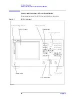
Names and Functions of Front Panel Blocks
2. Fun
ction
Overvie
w
1. Standby switch
Used to turn on/off the power to the E4991A.
NOTE
To turn off the power to the E4991A, be sure to press this power supply switch.
Alternatively, activate the E4991A shutdown process (i.e., software and hardware process
required to turn off the power) by sending a shutdown command from the external
controller.
You must never directly shut off the power supply by removing the power
cable from the receptacle on the rear panel.
If the power supply is directly shut off by removing the power cable, the shutdown process
is not activated, and this may damage the E4991A software and hardware, resulting in
operational failures.
If the E4991A shutdown process is not properly executed, the E4991A may restart in
safe mode. If this happens, activate the shutdown process to turn off the power to the
E4991A and then press the standby switch to turn the power on again.
For turning on/off the power, also refer to Chapter 1, “Installation Guide” in the
Installation and Quick Start Guide
.
2. 3.5-inch built-in floppy disk drive
This device is used to save the E4991A settings, measured data, calibration/compensation
data, image data displayed on the LCD display, VBA (Visual Basic for Applications)
programs, and other data to a floppy disk or to recall them. It works with 3.5-inch 1.44 MB
DOS formatted floppy disks.
The floppy disk access lamp is located to the left of the disk slot. It lights up in green when
the floppy disk drive accesses the disk by either read or write operation.
The disk eject button is located to the right of the disk slot. By pressing it, the currently
inserted disk can be ejected.
NOTE
Insert the floppy disk into the slot in the direction of the arrow denoted on the disk,
with
the labeled side facing the LCD display
.
Do not press the disk eject button while the floppy disk access lamp is lit.
If you
attempt to forcibly eject the disk, the disk or drive may be destroyed.
3. Color LCD display
This displays all of the information required to operate the E4991A (e.g., measurement
trace, settings, menu and setup bars). It is an 8.4-inch TFT type display.
For details on the information displayed on the LCD display, see “Names and Functions of
LCD Display Areas” on page 32.
4. Measurement block (MEASUREMENT)
This contains a set of keys that are used to set the basic measurement conditions, except for
the test signal settings. Pressing one of these keys brings up the associated toolbar to the
right of the display.
Summary of Contents for E4991A
Page 6: ......
Page 24: ...18 Contents ...
Page 80: ...74 Chapter3 Setting Measurement Conditions Averaging Measurement Results ...
Page 220: ...214 Chapter9 Setup and Use of Control Management Functions System Recovery ...
Page 338: ...332 AppendixB Probe Station Connection Kit Option 010 OPEN SHORT LOAD Calibration ...
Page 428: ...422 AppendixD Menu References Menu References ...
Page 482: ...476 AppendixI Messages Wait measuring comp standard ...

