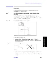
338
Appendix C
Temperature Characteristic Test Kit (Option 007)
Installation
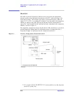
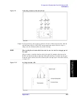
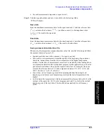
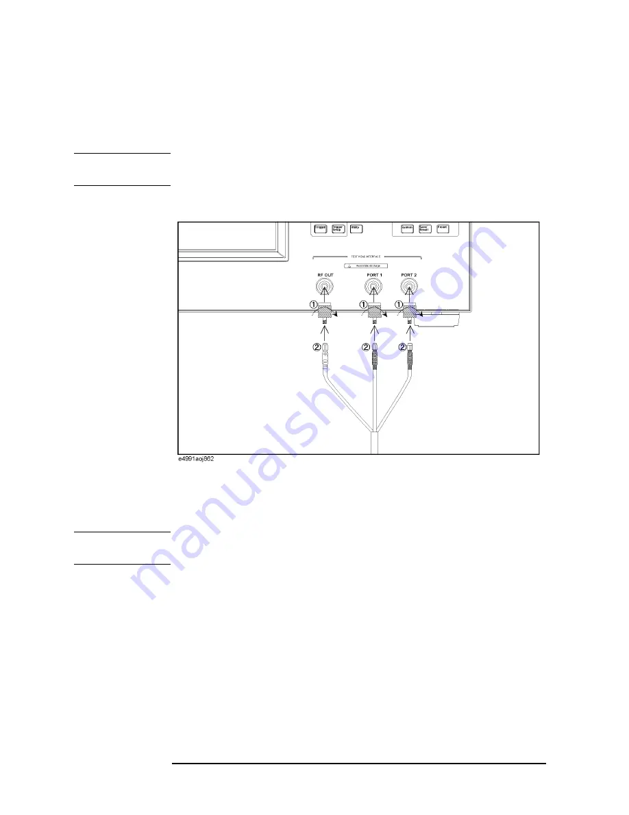
4. Connect the extension cable between the E4991A and the test head.
Step 1.
Connect the N (male) - 3.5 mm (female) adapters to RF Out, Port 1, and Port 2 on the
E4991A
and then connect the cables to the corresponding ports whose names are written
on the extension cable.
NOTE
To avoid damage to the connectors of the extension cable, be sure to connect the adapters
to the E4991A first, and then connect the extension cable to the adapters.
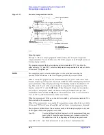
Figure C-8
Connecting extension cable and E4991A
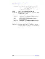
Step 2.
Connect the N (female) - 3.5 mm (female) adapters to RF Out, Port 1, and Port 2 on the test
head and then connect the cables to the corresponding ports whose names are written on
the extension cable.
NOTE
To avoid damage to the connectors of the extension cable, be sure to connect the adapters
to the test head first, and then connect the extension cable to the adapters.
Summary of Contents for E4991A
Page 6: ......
Page 24: ...18 Contents ...
Page 80: ...74 Chapter3 Setting Measurement Conditions Averaging Measurement Results ...
Page 220: ...214 Chapter9 Setup and Use of Control Management Functions System Recovery ...
Page 338: ...332 AppendixB Probe Station Connection Kit Option 010 OPEN SHORT LOAD Calibration ...
Page 428: ...422 AppendixD Menu References Menu References ...
Page 482: ...476 AppendixI Messages Wait measuring comp standard ...


