Chapter 2
29
Function Overview
Names and Functions of Rear Panel Blocks
2. Fun
ction
Overvie
w
1. Power cable receptacle (-LINE)
This is the receptacle for connection of the power cable.
For the requirements of the power supply, refer to Chapter 1, “Installation Guide” in the
Installation and Quick Start Guide
.
NOTE
For the power cable, use the attached 3-wire power cable with grounding prong. For
details, refer to Chapter 1, “Installation Guide” in the Installation and Quick Start Guide.
2. LAN port
Connector type: RJ-45J UTP (Unshielded Twisted Pair) LAN connector
Using this port, the E4991A can be connected to a Local Area Network (LAN). For how to
use the instrument in a LAN, refer to the
Programming Manual
.
3. Printer parallel port (PRINTER, Parallel)
This is a 25-pin parallel port used for connecting a printer. With the specified printer
connected to this port, you can print E4991A measurement graphs, measurement values
list, settings list, and other data. For the printers that can be used with the E4991A, see
“Supported Printers” on page 187.
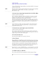
4. External trigger input connector (Ext Trig)
Connector type: BNC connector (female)
This is the terminal through which a trigger signal is input to begin execution of
measurement. It detects a trigger by the rising or falling edge following the Low or High
level of a TTL-compatible signal. To trigger measurement with a signal input to this
terminal, you must set the trigger source to EXTERNAL (external trigger input connector).
For details of the input signal requirements of this terminal, see “External trigger input
connector” on page 256.
5. External monitor output terminal (VIDEO)
Connector type: 15-pin VGA connector
This is the terminal used for connecting an external color monitor (display device). With a
color monitor connected to this terminal, the same information that is displayed on the
E4991A LCD display can be viewed on the monitor screen.
6. GPIB connector
This is a General Purpose Interface Bus (GPIB) connector. An auto-measurement system
can be constructed by connecting an external controller or other equipment via this
connector. For more details on auto-measurement systems that utilize a GPIB, refer to the
Programming Manual
.
7. High stability frequency reference output connector (Ref Oven,
Option 1D5 only)
Connector type: BNC connector (male)
Summary of Contents for E4991A
Page 6: ......
Page 24: ...18 Contents ...
Page 80: ...74 Chapter3 Setting Measurement Conditions Averaging Measurement Results ...
Page 220: ...214 Chapter9 Setup and Use of Control Management Functions System Recovery ...
Page 338: ...332 AppendixB Probe Station Connection Kit Option 010 OPEN SHORT LOAD Calibration ...
Page 428: ...422 AppendixD Menu References Menu References ...
Page 482: ...476 AppendixI Messages Wait measuring comp standard ...

