60
Chapter 3
Setting Measurement Conditions
Setting and Applying dc Bias
Setting and Applying dc Bias
Follow the procedure below to apply dc bias to the DUT.
Procedure
CAUTION
Whenever you connect a DUT to or disconnect it from the E4991A for measurement, you
must first turn off the dc bias or set the sweep to the hold state (in sweep hold state, dc bias
is not applied to the DUT). If this step is not taken, the dc bias may destroy the device.
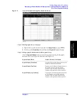
Step 1. Select the dc Bias Mode:
a.
Right-click to open the shortcut menu and click
Source
(or press
).
b.
Click to open the
Bias Source
box and then click to select the dc Bias Mode:
Step 2. Set the dc Bias Level
Use the numeric entry dialog box that appears by right-clicking inside the
Bias Level
box
(or the
ENTRY/NAVIGATION
block keys on the front panel) to enter the dcBias level.
Step 3. Set the dc Bias Limit
Use the numeric entry dialog box that appears by right-clicking inside the
Bias Limit
box
(or the
ENTRY/NAVIGATION
block keys on the front panel) to enter the dc Bias Limit
value.
Step 4. Apply dc Bias
a.
Click the
dc Bias
button and turn the dc Bias on.
If this operation is made during a sweep measurement, the sweep mode will
automatically stop the sweep. dc Bias will not be applied after the sweep is stopped.
b.
Execute sweep measurement according to the operating procedures described in
“Single Sweep, Continuous Sweep and Sweep Stop” on page 63.
Step 5. Monitor dc Bias Level
The level of dc bias applied to the DUT can be displayed by the following procedure.
a.
Right-click to open the shortcut menu and click
Source
(or press
).
b.
Click the
Bias Monitor
button and turn the dc bias level monitor on.
c.
Right-click to open the shortcut menu and click
Marker
.
Marker 1 appears on the trace and the dc bias level monitor value at the marker point is
displayed at the top of the screen area. For more details on setting and using markers,
refer to Chapter 6, “Analysis of Measurement Results,” on page 127.
Bias Source
Box
dc Bias Mode
Current
Current Source
Voltage
Voltage Source
Summary of Contents for E4991A
Page 6: ......
Page 24: ...18 Contents ...
Page 80: ...74 Chapter3 Setting Measurement Conditions Averaging Measurement Results ...
Page 220: ...214 Chapter9 Setup and Use of Control Management Functions System Recovery ...
Page 338: ...332 AppendixB Probe Station Connection Kit Option 010 OPEN SHORT LOAD Calibration ...
Page 428: ...422 AppendixD Menu References Menu References ...
Page 482: ...476 AppendixI Messages Wait measuring comp standard ...


