Chapter 4
81
Calibration and Compensation
Calibration and Compensation Using 7-mm Test Port as a Calibration
Reference Plane
4. Cal
ibra
tion
an
d
Comp
ensatio
n
Calibration and Compensation Using 7-mm Test Port as a
Calibration Reference Plane
In order to use the 7-mm test port as a calibration reference plane, the steps given in the
procedure below need to be carried out in the order listed.
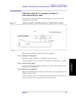
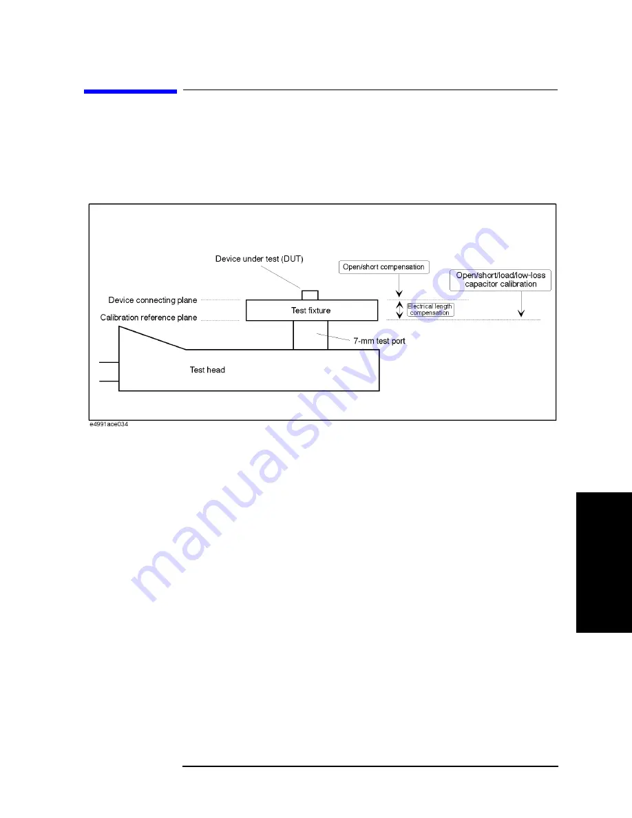
Figure 4-2
Calibration and Compensation using 7-mm Test Port as Calibration Reference Plane
Step 1. Definition of calibration/compensation
The definitions of the calibration kit and compensation kit to be used should be changed as
needed.
For more on this procedure, see “Definition of Calibration/Compensation Kit” on page 91.
Step 2. Open/short/load/low-loss capacitor calibration:
Measure calibration data of open/short/load with the 7-mm terminal of the test head. To
measure a device with high Q (low-loss factor) at a frequency higher than approx. 1 GHz,
calibration of low-loss capacitor needs to be done.
For more on this procedure, see “Calibration of Open/Short/Load/Low-loss Capacitor” on
page 84.
Step 3. Connection of test fixture
Connect the test fixture in front of the 7-mm terminal. For more on the connecting method,
see the fixture’s operation manual.
Step 4. Fixture’s electrical length compensation
The electrical length is set according to the kind of fixture used.
For more on this procedure, see “Electrical Length Compensation” on page 87.
Summary of Contents for E4991A
Page 6: ......
Page 24: ...18 Contents ...
Page 80: ...74 Chapter3 Setting Measurement Conditions Averaging Measurement Results ...
Page 220: ...214 Chapter9 Setup and Use of Control Management Functions System Recovery ...
Page 338: ...332 AppendixB Probe Station Connection Kit Option 010 OPEN SHORT LOAD Calibration ...
Page 428: ...422 AppendixD Menu References Menu References ...
Page 482: ...476 AppendixI Messages Wait measuring comp standard ...

