Appendix C
337
Temperature Characteristic Test Kit (Option 007)
Installation
C. T
e
m
per
atur
e
Char
acter
istic
Te
st Kit (
O
ption
007
)
2. Install the measurement cable in the temperature chamber.
Step 1.
Insert the measurement cable into the hole in the temperature chamber so that the Type L,
7-mm connector side faces the inside of the temperature chamber. Attach heat insulating
materials to the cable as necessary.
Step 2.
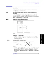
Adjust the position of the test fixture stand so that the length of the part of the measurement
cable that is exposed to air outside the temperature chamber (refer to Figure C-6) is 15 cm
or longer, and install the measurement cable to the stand.
Figure C-6
Installing measurement cable to test fixture stand
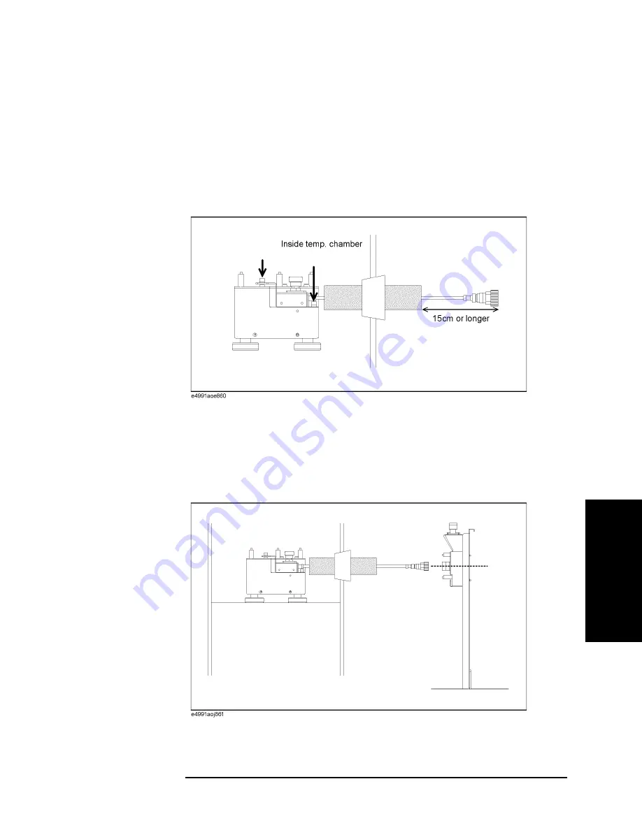
3. Connect the measurement cable to the test head.
Step 1.
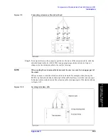
Adjust the position of the stand so that the 7-mm connector of the measurement cable and
the 7-mm connector of the test head (DUT port) are located at the same height. In this step,
fine adjust the position of the test head holder temporarily mounted and secure it tightly.
Figure C-7
Connecting measurement cable and test head
Step 2.
Connect the measurement cable and the test head.
Summary of Contents for E4991A
Page 6: ......
Page 24: ...18 Contents ...
Page 80: ...74 Chapter3 Setting Measurement Conditions Averaging Measurement Results ...
Page 220: ...214 Chapter9 Setup and Use of Control Management Functions System Recovery ...
Page 338: ...332 AppendixB Probe Station Connection Kit Option 010 OPEN SHORT LOAD Calibration ...
Page 428: ...422 AppendixD Menu References Menu References ...
Page 482: ...476 AppendixI Messages Wait measuring comp standard ...


