78
Chapter 4
Calibration and Compensation
Outline of Calibration and Compensation Functions
Calibration/Compensation measurement point mode
The
E4991A
has three modes for defining the measurement points when the calibration and
compensation data are measured.
User-defined frequency/User-defined power point mode
Obtain calibration/compensation data at the same frequency and power points as used in
actual device measurement, which are determined by the sweep setups. Each set of
calibration/compensation data is applied to each measurement at the same points.
Fixed frequency/fixed power point mode
Obtain calibration/compensation data in a fixed frequency (Table 4-4) and power (Table
4-5) range of the
E4991A
. In device measurement, calibration or compensation is applied to
each measurement point by using interpolation.
Fixed frequency/user-defined power point mode
Obtain calibration/compensation data at fixed frequency points (Table 4-4) covering the
entire frequency range of the E4991A and at the same power points used in actual device
Table 4-2
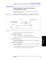
Calibration Reference Plane and Necessary Calibration/Compensation
Calibration Reference
Plane
Necessary Calibration/Compensation
Place and Method of Execution
7-mm terminal for test head
*1
(A)
1. Calibration for open/short/load
Connect the coaxial terminal calibration kit
to the coaxial terminal of the test head
(calibration reference plane).
2. Calibration of low-loss capacitor (This
calibration is only used for such cases as
high-Q measurement when high accuracy or
consideration of low-loss factor is required
at a frequency above approx. 1 GHz.)
Connect the low-loss capacitor to the
calibration reference plane.
*2
3. Compensation for a fixture’s electrical
length
Enter this electrical length into the Agilent
E4991A as data covering the area from the
calibration reference plane to the tested
device connecting plane.
*3
4. Compensation of open/short
Bring the tested device’s connecting
terminal into the open and short states.
Terminal for connecting to
the DUT (B)
Calibration of open/short/load
Connect the working standard
*4
to the
tested device’s connecting terminal to make
a calibration reference plane.
*1.In extending the coaxial cable from the 7-mm terminal of test head to the test fixture, it is possible to compensate
the port extension for the extended portion. For more on the port extension, see “Port Extension Compensation” on
page 86.
*2.Since the low-loss capacitor is the 7-mm type, this calibration can only be executed when the calibration reference
plane is a 7-mm terminal.
*3.When using an exclusive-use test fixture with a registered electrical length, you only need to select the model num-
ber of the fixture.
*4.This is a reference device that has a similar shape to the device under test.
Summary of Contents for E4991A
Page 6: ......
Page 24: ...18 Contents ...
Page 80: ...74 Chapter3 Setting Measurement Conditions Averaging Measurement Results ...
Page 220: ...214 Chapter9 Setup and Use of Control Management Functions System Recovery ...
Page 338: ...332 AppendixB Probe Station Connection Kit Option 010 OPEN SHORT LOAD Calibration ...
Page 428: ...422 AppendixD Menu References Menu References ...
Page 482: ...476 AppendixI Messages Wait measuring comp standard ...


