Chapter 4
101
Troubleshooting
Function Specific Troubleshooting
4. T
ro
uble
s
hoo
tin
g
To Check the Device Driver
Make sure first whether the E5052A device drivers are installed properly or not by the
following procedure, if a function of specific device in the E5052A doesn't work.
Step 1.
Exit from the E5052A measurement view in accordance with the procedure described in
“How to exit from the E5052A Measurement View” on page 85. Then, Windows desktop
screen is displayed.
Step 2.
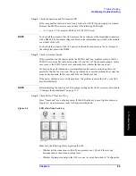
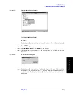
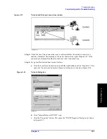
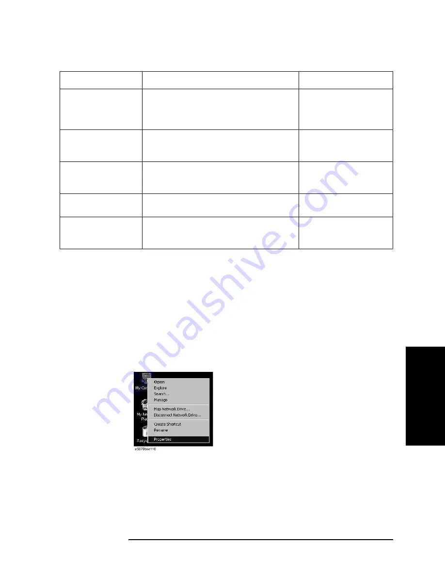
Click "My Computer" with the right button and select "Properties" as shown in Figure
4-17. Then, the System Properties(Figure 4-18) will appear.
Figure 4-17
Opening System Property Window
Printer parallel port
A specified printer can be used to print the
E5052A measurement display, setup display and
others, when it is connected to the Printer port
(36-pin D-Sub) on the rear panel.
Refer to “To Check the
Printer Parallel/USB Port”
on page 110.
GPIB Interface
The GPIB compatibility allows the E5052A to be
operated as a talker/listener on IEEE 488 interface
bus.
Refer to “To Check the
GPIB” on page 111.
24-bit I/O port
The 24-bit I/O port can be used to transfer a
comparator decision output data to and perform
timing synchronization with an external handler.
Refer to in “To Check the
24-bit I/O port” on page 111.
Ref Oven
A 10 MHz high stability signal is outputted.
Refer to in “To Check the
Ref Oven” on page 111.
USB (USBTMC)
Interface
The GPIB compatibility allows the E5052A to be
operated as a talker/listener on IEEE 488 interface
bus.
Refer to in “To Check the
USB (USBTMC) Interface
Card” on page 111.
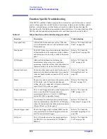
Table 4-2
Major functions and troubleshooting procedures
Function
Description
Troubleshooting
Summary of Contents for E5052A
Page 13: ...Contents 13 M 271 N 271 O 271 P 271 R 272 S 273 T 273 U 273 ...
Page 14: ...14 Contents ...
Page 22: ...22 Chapter1 General Information Required Equipment ...
Page 46: ...46 Chapter2 Performance Tests Individual Test Description Step 17 Turn off the power of AMP2 ...
Page 82: ...82 Chapter3 Adjustment Required Adjustment after Replacing Assembly ...
Page 218: ...216 Chapter6 Replacement Procedure A51 LCD Replacement Figure 6 27 A51 LCD Removal ...
Page 222: ...220 Chapter6 Replacement Procedure BNC Connector front Replacement ...
Page 244: ...242 AppendixB System Recovery Calibration of the Touch Screen ...
Page 250: ...248 AppendixC Firmware Update Firmware Update ...
Page 261: ...259 E Power Requirement E Power Requirement ...

