26
Chapter 2
Performance Tests
Individual Test Description
Step 2.
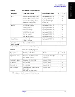
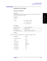
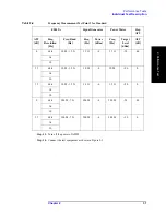
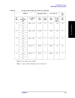
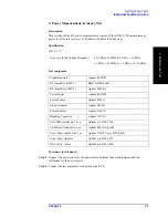
Set the values as shown below.
Step 3.
Perform the 1-port calibration for port 1. The calibration kit (open/short/load) is connected
to the end of the N-N cable connected to port 1.
Step 4.
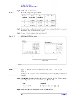
Connect the test equipment as shown in Figure 2-1.
Figure 2-1
RF IN port VSWR test setup
NOTE
Figure 2-1 shows the test setup for the Network Analyzer with 4-port option (opt.
413/414).
For 2-port and 3-port options (opt. 213/214/313/314), connect the N(m)-N(m) cable to port
1 as well.
Step 5.
Press
[Preset]
-
Factory
to initialize the E5052A, then set the E5052A as follows. In case
of installing the firmware revision 1.00/1.10, press
[Preset]
-
OK
.
Step 6.
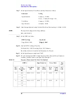
Make the single sweep measurement for the Network Analyzer.
Table 2-2
Network Analyzer Segment Table
Segment
Number
Start
Frequency
Stop
Frequency
point
Power
1
10 MHz
39.5 MHz
60
10 dBm
2
40 MHz
99 MHz
60
10 dBm
3
100 MHz
3 GHz
294
10 dBm
Setting
Operation
Attenuator : 0 dB
[Attn]
-
Input Attenuator
-
[0]
-
[x1]
Summary of Contents for E5052A
Page 13: ...Contents 13 M 271 N 271 O 271 P 271 R 272 S 273 T 273 U 273 ...
Page 14: ...14 Contents ...
Page 22: ...22 Chapter1 General Information Required Equipment ...
Page 46: ...46 Chapter2 Performance Tests Individual Test Description Step 17 Turn off the power of AMP2 ...
Page 82: ...82 Chapter3 Adjustment Required Adjustment after Replacing Assembly ...
Page 218: ...216 Chapter6 Replacement Procedure A51 LCD Replacement Figure 6 27 A51 LCD Removal ...
Page 222: ...220 Chapter6 Replacement Procedure BNC Connector front Replacement ...
Page 244: ...242 AppendixB System Recovery Calibration of the Touch Screen ...
Page 250: ...248 AppendixC Firmware Update Firmware Update ...
Page 261: ...259 E Power Requirement E Power Requirement ...

