40
Chapter 2
Performance Tests
Individual Test Description
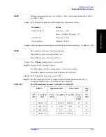
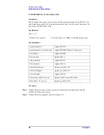
Step 13.
Turn off the power of AMP1.
Step 14.
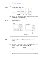
Connect the test equipment as shown in Figure 2-7
Figure 2-7
Power Measurement Accuracy Test setup 2 for Standard
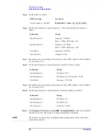
Step 15.
Turn on the power of AMP2.
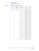
5
10 M - 1.5 G
-4
10 M
10 M
+10
10
5
10 M - 1.5 G
1 G
1 G
10
5
300 M - 7 G
2.0125 G
2.0125 G
10
15
10 M - 1.5 G
-6
10 M
10 M
+20
0
15
10 M - 1.5 G
1 G
1 G
0
15
300 M - 7 G
2.0125 G
2.0125 G
0
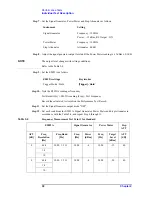
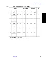
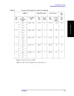
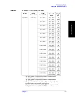
Table 2-8
Power Measurement Accuracy Test Point 1 for Standard
E5052A
Signal Generator
Power Meter
Step
ATT
ATT
[dB]
Freq Band
[Hz]
Power
[dBm]
Freq [Hz]
Freq [Hz]
Target
Level
[dBm]
ATT
[dB]
Summary of Contents for E5052A
Page 13: ...Contents 13 M 271 N 271 O 271 P 271 R 272 S 273 T 273 U 273 ...
Page 14: ...14 Contents ...
Page 22: ...22 Chapter1 General Information Required Equipment ...
Page 46: ...46 Chapter2 Performance Tests Individual Test Description Step 17 Turn off the power of AMP2 ...
Page 82: ...82 Chapter3 Adjustment Required Adjustment after Replacing Assembly ...
Page 218: ...216 Chapter6 Replacement Procedure A51 LCD Replacement Figure 6 27 A51 LCD Removal ...
Page 222: ...220 Chapter6 Replacement Procedure BNC Connector front Replacement ...
Page 244: ...242 AppendixB System Recovery Calibration of the Touch Screen ...
Page 250: ...248 AppendixC Firmware Update Firmware Update ...
Page 261: ...259 E Power Requirement E Power Requirement ...

