176
Chapter 6
Replacement Procedure
Outer Cover Removal
Outer Cover Removal
Tools Required
•
TORX screwdriver, T10,T15 and T20
Procedure
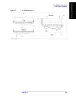
Refer to Figure 6-1 for this procedure.
Step 1.
Disconnect the power cable from the E5052A.
Step 2.
Remove the four TORX T15 screws (item 6) fastening the four rear foot
Step 3.
Remove the four TORX T15 screws (item 9) fastening the cover.
Step 4.
Remove the four TORX T20 screws (item 1,4) fastening the side strap handles.
Step 5.
Remove the four bottom feet (item 3, 5).
Step 6.
Remove the four TORX T10 screws (item 8) from the bottom.
Step 7.
Slide the outer cover and remove it carefully.
Summary of Contents for E5052A
Page 13: ...Contents 13 M 271 N 271 O 271 P 271 R 272 S 273 T 273 U 273 ...
Page 14: ...14 Contents ...
Page 22: ...22 Chapter1 General Information Required Equipment ...
Page 46: ...46 Chapter2 Performance Tests Individual Test Description Step 17 Turn off the power of AMP2 ...
Page 82: ...82 Chapter3 Adjustment Required Adjustment after Replacing Assembly ...
Page 218: ...216 Chapter6 Replacement Procedure A51 LCD Replacement Figure 6 27 A51 LCD Removal ...
Page 222: ...220 Chapter6 Replacement Procedure BNC Connector front Replacement ...
Page 244: ...242 AppendixB System Recovery Calibration of the Touch Screen ...
Page 250: ...248 AppendixC Firmware Update Firmware Update ...
Page 261: ...259 E Power Requirement E Power Requirement ...


