Chapter 6
181
Replacement Procedure
A27 Mass storage Disk Drive Assembly Replacement
6. Re
placem
ent Pro
c
e
d
u
re
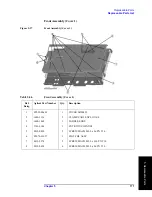
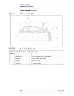
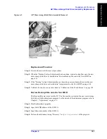
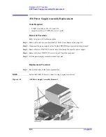
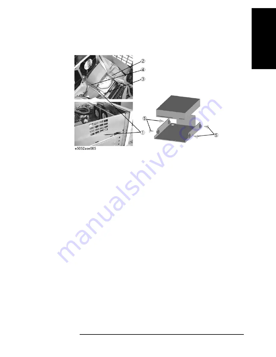
Figure 6-3
A27 Mass storage Disk Drive Assembly Removal
Replacement Procedure
Step 1.
Reverse the order of the removal procedure.
Step 2.
When the “Backup” in Spot Adjustment has been done, restore backup files onto the new
mass storage disk drive as described in “Restore Backup Files onto the New HDD” on
page 181.
Step 3.
If the “Backup” in Spot Adjustment has not been done, restore backup files onto the new
mass storage disk drive as described in “Adjustments for the New HDD” on page 182.
Step 4.
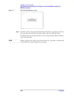
Calibrate the touch screen as described in “Calibration of the Touch Screen” on page 182.
Restore Backup Files onto the New HDD
The Backup files are stored into the PC. The file must be restored in the new mass storage
disk drive with the adjustment program. For the details of the adjustment program, refer to
Chapter 3, “Adjustment,” on page 73.
Step 1.
Run the adjustment program.
Step 2.
Input the GPIB address of the E5052A.
Step 3.
Input the serial number of the E5052A.
Step 4.
Perform the adjustment using “Recovery” in
Spot Adjustment
of the program.
Summary of Contents for E5052A
Page 13: ...Contents 13 M 271 N 271 O 271 P 271 R 272 S 273 T 273 U 273 ...
Page 14: ...14 Contents ...
Page 22: ...22 Chapter1 General Information Required Equipment ...
Page 46: ...46 Chapter2 Performance Tests Individual Test Description Step 17 Turn off the power of AMP2 ...
Page 82: ...82 Chapter3 Adjustment Required Adjustment after Replacing Assembly ...
Page 218: ...216 Chapter6 Replacement Procedure A51 LCD Replacement Figure 6 27 A51 LCD Removal ...
Page 222: ...220 Chapter6 Replacement Procedure BNC Connector front Replacement ...
Page 244: ...242 AppendixB System Recovery Calibration of the Touch Screen ...
Page 250: ...248 AppendixC Firmware Update Firmware Update ...
Page 261: ...259 E Power Requirement E Power Requirement ...


