background image

182

Chapter 6


Replacement Procedure

A27 Mass storage Disk Drive Assembly Replacement

Adjustments for the New HDD

Step 1.

Run the adjustment program.

Step 2.

Input the GPIB address of the E5052A.

Step 3.

Input the serial number of the E5052A.

Step 4.

Perform the adjustment using “HDD” in 

Spot Adjustment

 of the program.

Calibration of the Touch Screen

When you have replaced the HDD on a E5052A, you have to calibrate the touch screen. 
Follow the procedure described below to calibrate the touch screen. 

Step 1.

Press [System].

Step 2.

Press 

Service Menu

.

Step 3.

Press 

Test Menu

.

Step 4.

Press 

Adjust Touch Screen

.

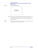
 The touch screen calibration screen (Figure 6-4) appears.

Figure 6-4 

Touch Panel Calibration Screen

Step 5.

Touch the x mark on the upper left with your finger. The mark x appears also on the lower 
left, upper right, and lower right. Touch the x marks in that order with your finger.

Touching the four locations described above with your finger automatically concludes the 
touch screen calibration.

NOTE

With no operation on the touch screen calibration screen for a preset time, it automatically 
closes and the previous measurement screen reappears.

Summary of Contents for E5052A

Page 1: ...Agilent E5052A Signal Source Analyzer Service Guide Sixth Edition Manufacturing No E5052 90150 November 2007 ...

Page 2: ...5 2006 2007 Agilent Technologies Manual Printing History The manual s printing date and part number indicate its current edition The printing date changes when a new edition is printed Minor corrections and updates that are incorporated at reprint do not cause the date to change The manual part number changes when extensive technical changes are incorporated November 2004 First Edition February 20...

Page 3: ...ments are to be confirmed by the builder of the system Ground the Instrument To avoid electric shock the instrument chassis and cabinet must be grounded with the supplied power cable s grounding prong DO NOT Operate in an Explosive Atmosphere Do not operate the instrument in the presence of inflammable gasses or fumes Operation of any electrical instrument in such an environment clearly constitute...

Page 4: ...to refer to the instrument manual Alternating current Direct current On Supply Off Supply In position of push button switch Out position of push button switch Frame or chassis terminal A connection to the frame chassis of the equipment which normally include all exposed metal structure Stand by WARNING This warning sign denotes a hazard It calls attention to a procedure practice condition or the l...

Page 5: ...to the implied warranties of merchantability and fitness for a particular purpose Agilent shall not be liable for errors or for incidental or consequential damages in connection with the furnishing use or performance of this document or any information contained herein Should Agilent and the user have a separate written agreement with warranty terms covering the material in this document that conf...

Page 6: ...d labeled Sample key may be omitted Sample menu button box Indicates a menu button box on the screen labeled Sample which can be selected executed by clicking menu button or box may be omitted Sample block toolbar Indicates a block group of hardkeys or a toolbar setup toolbar labeled Sample Sample 1 Sample 2 Sample 3 Indicates a sequential operation of Sample 1 Sample 2 and Sample 3 menu button or...

Page 7: ...052A Performance Test Record 66 RF IN Port VSWR Test 66 Frequency Measurement Test 66 Power Measurement Accuracy Test 68 SSB Phase Noise Sensitivity Test for Standard 70 SSB Phase Noise Sensitivity Test for Option 011 70 SA Relative Level Accuracy Test 70 DC Power Voltage Test 72 DC Current Measurement Test 72 3 Adjustment Safety Considerations 74 Warm up for Adjustment 74 Required Equipment 74 Re...

Page 8: ...k the FDD 105 To Check the Video output 106 To Check the External Trigger Input 106 To Check the LAN 106 To Check the Printer Parallel USB Port 110 To Check the GPIB 111 To Check the 24 bit I O port 111 To Check the Ref Oven 111 To Check the USB USBTMC Interface Card 111 Performance test failure troubleshooting 112 Recommended adjustment for performance test failure 112 Adjustment failure troubles...

Page 9: ... Disk Drive Assembly for Serial Prefix MY441 153 Removable Hard Disk Assembly for Serial Prefix MY442 154 Analog Mother Board Assembly 156 Power Supply Assembly 157 Power Distribution and Oven Assembly 158 Freq Power Detector Module Attachment Assembly 159 DC Source Board Attachment Assembly 160 Local Synthesize Module Assembly 161 Phase Detector Board Assembly 162 Chassis Assembly 163 Front Assem...

Page 10: ... Removal procedure 189 Replacement Procedure 189 A50 Power Supply Assembly Replacement 190 Tools Required 190 Removal Procedure 190 Replacement Procedure 190 A25 24 Bit I O Board Replacement 191 Tools Required 191 Removal Procedure 191 Replacement Procedure 191 A20 Digital Motherboard Replacement 192 Tools Required 192 Removal Procedure 192 Replacement Procedure 192 A1 Freq Power Detector Module R...

Page 11: ... Replacement Procedure 205 A21 PCI DSP A24 GPIB Card Replacement for Serial Prefix MY442 and above 207 Tools Required 207 Removal Procedure 207 Replacement Procedure 207 USB USBTMC Interface Card Replacement for E5052A Serial Prefix MY442 and above 209 Tools Required 209 Removal Procedure 209 Replacement Procedure 209 A22 Front Keyboard Replacement 211 Tools Required 211 Removal Procedure 211 Repl...

Page 12: ...2A 238 Calibration of the Touch Screen 241 C Firmware Update Firmware Update 244 Required Equipment 244 How to make E5052A Firmware Installation Disk 244 How to update the E5052A firmware 244 D Computer Virus Check Computer Virus Check 250 Required equipment 250 How to check the drive C and F of E5052A 250 E Power Requirement Power Supply and Blown Fuses 260 Verification of the power supply 260 Ve...

Page 13: ...Contents 13 M 271 N 271 O 271 P 271 R 272 S 273 T 273 U 273 ...

Page 14: ...14 Contents ...

Page 15: ...Information 1 General Information The Service Guide is a guide to servicing the E5052A Signal Source Analyzer The guide contains information requisite to do performance tests adjustments troubleshooting and repairs ...

Page 16: ...e the followings Do not update the Windows operating system installed in this machine to the Windows operating system for ordinary PCs Doing so will cause malfunctions Do not attempt to update VBA Visual Basic for Applications software installed in this machine to its equivalent developed for ordinary PCs Doing so will cause malfunctions Do not allow any computer virus to infect the system This ma...

Page 17: ...ting This chapter provides the procedure to isolate a faulty assembly in the E5052A Chapter 5 Replaceable Parts This chapter contains information for ordering replacement parts for the E5052A Chapter 6 Replacement Procedure This chapter provides procedure for removing and replacing the major assemblies in the E5052A Chapter 7 Post Repair Procedures This chapter lists the procedures required to ver...

Page 18: ... check the system of E5052A for computer viruses using computer viruses check software Appendix E Power Requirement Appendix F Messages The E5052A can display error messages as well as messages that indicate the internal operating status of the equipment This appendix explains what these messages mean They are listed in alphabetical order ...

Page 19: ...ed by a yellow Manual Changes supplement or have a different manual part number This sheet contains change information that explains how to adapt the manual to the newer instrument In addition to change information the supplement may contain information for correcting errors Errata in the manual To keep this manual as current and accurate as possible Agilent Technologies recommends that you period...

Page 20: ...0A 1 P A Multimeter No Substitute Agilent 3458A 1 P A Calibration Kit Frequency 10 M to 7 GHz Agilent 85032F 1 P Frequency Counter Frequency 10 MHz Agilent 53181A w Opt 010 1 T Step Attenuator Attenuator range 0 dB to 50 dB Step 10dB Freq range 10 M to 7 GHz Agilent 8496H 1 P A Blocking Capacitor No Substitute Agilent 11742A 1 P A Power divider No substitute Agilent 11636A 1 P Fixed attenuator 3 d...

Page 21: ... Size 3 4 inch Torque 136 N cm Agilent p n 8710 1766 1 P A Personal Computer with GPIB board Windows 2000 VEE 6 0 1 A 1 P Performance Tests A Adjustment T Troubleshooting Table 1 2 Alternative Test Equipment Equipment Critical specifications Model Qty Use 1 Signal Generator Frequency 10 MHz to 7 GHz Low SSB Phase Noise Agilent E8257C w Opt UNR UNT 1 P A Network Analyzer Frequency 10 M to 3 GHz Agi...

Page 22: ...22 Chapter1 General Information Required Equipment ...

Page 23: ...23 2 Performance Test 2 Performance Tests This chapter provides information on how to verify the E5052A performance ...

Page 24: ...terval is 12 months The test interval depends on maintenance and the environmental conditions under which the instrument is used You may find that the interval could be shortened or lengthened however such a decision should be based on substantial quantitative data Test Equipment Required The required equipment for the performance test is listed in Table 1 1and Table 1 2 Use only calibrated equipm...

Page 25: ...cification 23 5 C Test equipment Procedure Step 1 Preset the Network Analyzer Then set the Network Analyzer as follows VSWR 1 6 10 MHz to 30 MHz 1 2 30 MHz to 2 GHz 1 3 2 GHz to 3 GHz Network Analyzer Agilent E5070B 5071B Calibration Kit Agilent 85032F N m N m cable 61 cm Agilent N6314A p n 8120 8862 Parameter Value Measurement Mode S11 Cal Kit 85032F Trigger Sweep Hold Sweep Type Segment Source P...

Page 26: ...alyzer with 4 port option opt 413 414 For 2 port and 3 port options opt 213 214 313 314 connect the N m N m cable to port 1 as well Step 5 Press Preset Factory to initialize the E5052A then set the E5052A as follows In case of installing the firmware revision 1 00 1 10 press Preset OK Step 6 Make the single sweep measurement for the Network Analyzer Table 2 2 Network Analyzer Segment Table Segment...

Page 27: ...of maximum for the Network Analyzer Step 9 Record the VSWR in the Performance Test Record Test result column for the RF input impedance test Step 10 Set the E5052A as follows and repeat Step 6 through 9 Table 2 3 Network Analyzer Search Range Table Search Position Start Frequency Stop Frequency 1 10 MHz 30 MHz 2 30 MHz 2 GHz 3 2 GHz 3 GHz Setting Operation Attenuator 5 dB Attn Input Attenuator 5 x...

Page 28: ...ect the test equipment as shown in Figure 2 2 Frequency accuracy resolution time base accuracy 10 MHz to 7 GHz Frequency Resolution 10 Hz 1 kHz and 64 kHz Internal time base stability 5 ppm Signal Generator Agilent E8257D RF Amplifier AMP 1 R K A3000 2H R RF Amplifier AMP 2 Agilent 83020A Power Meter Agilent E4419B Power Sensor Agilent 8481A Step Attenuator Agilent 8496H Power Splitter Agilent 116...

Page 29: ...of AMP1 Step 6 Set the E5052A as follows E5052A settings Key strokes Measurement View FP Freq Meas View Freq Power Mode Tester Trigger Mode Tester Trigger Mode Hold Trigger Trigger to Freq Power Hold Attenuator 0 dB Attn Input Attenuator 0 x1 Averaging Factor 10 Avg BW Ave Factor 1 0 x1 Averaging ON Ave BW Averaging ON Averaging Trigger ON Trigger Ave Trigger ON E5052A settings Key strokes Frequen...

Page 30: ...Test Record Step 11 Set the Signal Generator output mode OFF Step 12 Set each conditions for E5052A Signal Generator Power Meter and Step Attenuator in accordance with the Table 2 4 and repeat Step 6 through 11 Instrument Setting Signal Generator Frequency 10 MHz Power 15 dBm RF Output ON Power Meter Frequency 10 MHz Step Attenuator Attenuator 40 dB E5052A settings Key strokes Trigger Mode Hold Tr...

Page 31: ...5 G 4 1 5 G 20 40 1 k 10 15 64 k 10 M 1 5 G 10 M 6 10 M 20 0 1 k 10 15 64 k 10 M 1 5 G 1 5 G 6 1 5 G 20 0 1 k 10 0 64 k 300 M 7 G 300 M 4 300 M 20 40 1 k 10 15 64 k 300 M 7 G 300 M 6 300 M 20 0 1 k 10 Table 2 4 Frequency Measurement Test Point 1 for Standard E5052A Signal Generator Power Meter Step ATT ATT dB Freq Resolution Hz Freq Band Hz Freq Hz Power dBm Freq Hz Target Level dBm ATT dB ...

Page 32: ...7 Turn off the power of AMP2 Procedure for Option 011 Step 1 Connect the power sensor to the power meter Perform the zero adjustment and the calibration for the power meter Step 2 Connect the test equipment as shown in Figure 2 4 Table 2 5 Frequency Measurement Test Point 2 for Standard E5052A Signal Generator Power Meter Step ATT ATT dB Freq Resolution Hz Freq Band Hz Freq Hz Power dBm Freq Hz Ta...

Page 33: ... Turn on the power of AMP1 Step 6 Set the E5052A as follows E5052A settings Key strokes Measurement View FP Meas View Freq Power Trigger Mode Hold Trigger Trigger to Freq Power Hold Attenuator 0 dB Atten Input Attenuator 0 x1 Averaging Factor 10 Avg BW Ave Factor 1 0 x1 Averaging ON Ave BW Averaging ON Averaging Trigger ON Trigger Ave Trigger ON E5052A settings Key strokes Frequency Band 10 M 1 5 ...

Page 34: ... Test Record Step 11 Set the Signal Generator output mode OFF Step 12 Set each conditions for E5052A Signal Generator Power Meter and Step Attenuator in accordance with the Table 2 6 and repeat Step 6 through 11 Instrument Setting Signal Generator Frequency 10 MHz Power 15 dBm RF Output ON Power Meter Frequency 10 MHz Step Attenuator Attenuator 40 dB E5052A settings Key strokes Trigger Mode Hold T...

Page 35: ... G 4 1 5 G 20 40 1 k 10 15 64 k 10 M 1 5 G 10 M 6 10 M 20 0 1 k 10 15 64 k 10 M 1 5 G 1 5 G 6 1 5 G 20 0 1 k 10 0 64 k 300 M 7 G 300 M 4 300 M 20 40 1 k 10 15 64 k 300 M 7 G 300 M 6 300 M 20 0 1 k 10 Table 2 6 Frequency Measurement Test Point 1 for Option 011 E5052A Signal Generator Power Meter Step ATT ATT dB Freq Resolution Hz Freq Band Hz Freq Hz Power dBm Freq Hz Target Level dBm ATT dB ...

Page 36: ...nerator Power meter and Step ATT in accordance with the Table 2 7 and repeat Step 6 through 11 Step 17 Turn off the power of AMP2 Table 2 7 Frequency Measurement Test Point 2 for Option 011 E5052A Signal Generator Power Meter Step ATT ATT dB Freq Resolution Hz Freq Band Hz Freq Hz Power dBm Freq Hz Target Level dBm ATT dB 0 64 k 300 M 7 G 7 G 4 7 G 20 40 1 k 10 15 64 k 300 M 7 G 7 G 6 7 G 20 0 1 k...

Page 37: ... the power meter Step 2 Connect the test equipment as shown in Figure 2 6 Accuracy Peak Voltage Response 0 5 dB 30 MHz to 3 GHz 10 dBm 1 dB 30MHz or 3 GHz or 10 dBm Signal Generator Agilent E8257D RF Amplifier AMP 1 R K A3000 2H R RF Amplifier AMP 2 Agilent 83020A Power Meter Agilent E4419B Power Sensor Agilent 8481A Step Attenuator Agilent 8496H Power Splitter Agilent 11667A Blocking Capacitor Ag...

Page 38: ...and Power Meter Step 5 Turn on the power of AMP1 Step 6 Set the E5052A as follows NOTE When measurement frequency is 300 MHz to 7 GHz set Frequency Band of the E5052A to 300M 7GHz E5052A settings Key strokes Measurement View FP Power Meas View Freq Power Mode Tester Trigger Mode Tester Trigger Mode Hold Trigger Trigger to Freq Power Hold E5052A settings Key strokes Frequency Band 10 M 1 5 GHz Setu...

Page 39: ...esult on the Performance Test Record Step 11 Set the Signal Generator output mode OFF Step 12 Set each conditions for E5052A Signal Generator Power Meter and Step ATT in accordance with the Table 2 8 and repeat Step 6 through 11 Instrument Setting Signal Generator Frequency 1 GHz Power 20 dBm RF Output ON Power Meter Frequency 1 GHz Step Attenuator Attenuator 30 dB Table 2 8 Power Measurement Accu...

Page 40: ...2 for Standard Step 15 Turn on the power of AMP2 5 10 M 1 5 G 4 10 M 10 M 10 10 5 10 M 1 5 G 1 G 1 G 10 5 300 M 7 G 2 0125 G 2 0125 G 10 15 10 M 1 5 G 6 10 M 10 M 20 0 15 10 M 1 5 G 1 G 1 G 0 15 300 M 7 G 2 0125 G 2 0125 G 0 Table 2 8 Power Measurement Accuracy Test Point 1 for Standard E5052A Signal Generator Power Meter Step ATT ATT dB Freq Band Hz Power dBm Freq Hz Freq Hz Target Level dBm ATT ...

Page 41: ...G 40 0 300 M 7 G 6 0125 G 6 0125 G 40 0 300 M 7 G 7 G 7 G 40 0 300 M 7 G 4 3 0125 G 3 0125 G 10 30 0 300 M 7 G 4 0125 G 4 0125 G 30 0 300 M 7 G 5 0125 G 5 0125 G 30 0 300 M 7 G 6 0125 G 6 0125 G 30 0 300 M 7 G 7 G 7 G 30 0 300 M 7 G 4 3 0125 G 3 0125 G 0 20 0 300 M 7 G 4 0125 G 4 0125 G 20 0 300 M 7 G 5 0125 G 5 0125 G 20 0 300 M 7 G 6 0125 G 6 0125 G 20 0 300 M 7 G 7 G 7 G 20 5 300 M 7 G 4 3 0125...

Page 42: ...3 Press Preset Factory to initialize the E5052A then set the E5052A as follows In case of installing the firmware revision 1 00 1 10 press Preset OK Step 4 Preset the Signal Generator and Power Meter Step 5 Turn on the power of AMP1 Step 6 Set the E5052A as follows E5052A settings Key strokes Measurement View FP Power Meas View Freq Power Trigger Mode Hold Trigger Trigger to Freq Power Hold E5052A...

Page 43: ...s Power Test Result dB E5052A reading Power Power Meter reading Record the calculated test result on the Performance Test Record Step 11 Set the Signal Generator output mode OFF Step 12 Set each conditions for E5052A Signal Generator Power Meter and Step ATT in accordance with the Table 2 10 and repeat Step 6 through 11 Instrument Setting Signal Generator Frequency 1 GHz Power 20 dBm RF Output ON ...

Page 44: ...A Signal Generator Power meter and Step ATT in 0 10 M 1 5 G 4 10 M 10 M 0 20 0 10 M 1 5 G 1 G 1 G 20 0 300 M 7 G 2 0125 G 2 0125 G 20 5 10 M 1 5 G 4 10 M 10 M 10 10 5 10 M 1 5 G 1 G 1 G 10 5 300 M 7 G 2 0125 G 2 0125 G 10 15 10 M 1 5 G 6 10 M 10 M 20 0 15 10 M 1 5 G 1 G 1 G 0 15 300 M 7 G 2 0125 G 2 0125 G 0 Table 2 10 Power Measurement Accuracy Test Point 1 for Option 011 E5052A Signal Generator ...

Page 45: ...00 M 7 G 7 G 7 G 40 0 300 M 7 G 4 3 0125 G 3 0125 G 10 30 0 300 M 7 G 4 0125 G 4 0125 G 30 0 300 M 7 G 5 0125 G 5 0125 G 30 0 300 M 7 G 6 0125 G 6 0125 G 30 0 300 M 7 G 7 G 7 G 30 0 300 M 7 G 4 3 0125 G 3 0125 G 0 20 0 300 M 7 G 4 0125 G 4 0125 G 20 0 300 M 7 G 5 0125 G 5 0125 G 20 0 300 M 7 G 6 0125 G 6 0125 G 20 0 300 M 7 G 7 G 7 G 20 5 300 M 7 G 4 3 0125 G 3 0125 G 10 10 5 300 M 7 G 4 0125 G 4 ...

Page 46: ...46 Chapter2 Performance Tests Individual Test Description Step 17 Turn off the power of AMP2 ...

Page 47: ...fset from carrier Hz 1 k 10 k 100 k 1 M 10 M 40 M 10 MHz 148 5 156 5 166 5 168 5 100 MHz 148 5 156 5 163 5 168 5 170 0 1 GHz 128 5 137 5 144 5 160 5 170 0 170 0 3 GHz 119 0 128 0 133 7 149 7 163 2 166 7 7 GHz 111 6 120 6 127 0 143 0 156 5 160 0 Input Frequency Offset from carrier Hz 1 k 10 k 100 k 1 M 10 M 40 M 10 MHz 145 5 153 5 160 0 160 0 100 MHz 145 5 153 5 160 0 160 0 160 0 1 GHz 125 5 134 5 ...

Page 48: ...2 12 for Option 011 Table 2 13 Table 2 12 E5052A Settings Value for Standard E5052A settings Key strokes Trigger Mode Hold Trigger Trigger to Phase Noise Hold Frequency Band 39 M 101 MHz Setup Frequency Band 39M 101MHz Start Frequency 1 Hz Start Center 1Hz Stop Frequency 10 MHz Stop Span 10MHz IF Gain 50 dB Setup IF Gain 5 0 x1 Correlation 1 Avg BW Correlation 1 x1 Attenuator 0 dB Attn Input Atten...

Page 49: ...Value for Option 011 E5052A settings Key strokes Trigger Mode Hold Trigger Trigger to Phase Noise Hold Frequency Band 39 M 101 MHz Setup Frequency Band 39M 101MHz Start Frequency 100 Hz Start Center 100Hz Stop Frequency 10 MHz Stop Span 10MHz Attenuator 0 dB Attn Input Attenuator 0 x1 Maker 1 s Position 1 MHz Marker Marker 1 1 M u Maker 2 s Position 3 MHz Marker Marker 2 3 M u Maker 3 s Position 7...

Page 50: ...Perform the zero adjustment and the calibration for the power meter Step 2 Connect the test equipment as shown in Figure 2 11 Relative level accuracy 1 5 dB ratio of 10 dBm to 60 dBm during sweep Signal Generator 1 Agilent E8257D Signal Generator 2 or Sweeper Agilent E5070B 71B use of the source Power Meter Agilent E4419B Power Sensor Agilent 8481A Step Attenuator Agilent 8496H Power Splitter Agil...

Page 51: ...gs Key strokes Measurement View SP Meas View Spectrum Monitor Trigger Mode Hold Trigger Trigger to Spectrum Monitor Hold Attenuator 0 dB Attn Input Attenuator 0 x1 SPAN 15 MHz Stop Span Span 1 5 M u RBW 1562 5 Hz Avg BW RBW 1 5 6 2 5 x1 Number of Average 16 Avg Bw Avg Factor 1 6 x1 Averaging Mode ON Avg BW Averaging ON off Maker Display ON Marker Marker 1 Check Search Range X Mode Bandmarker Marke...

Page 52: ...s Trigger Continuous and Avg BW Averaging Restart to make a measurement Wait until a trace for the average of 16 swept measurements is displayed NOTE The number of averaging times is displayed in the averaging status lower right of the measurement windows E5052A settings Key strokes Center Frequency 100 MHz Start Center Center 1 0 0 M u Instrument Setting Signal Generator 1 Frequency 100 MHz Power...

Page 53: ... the E5052A reading in the calculation sheet SA2 column for the SA Relative Level Accuracy Test Step 16 Calculate the following formula Test Result dB SA2 SA1 PM2 PM1 Cal value of Step attenuator SATT Record the test result on the Performance Test Record Step 17 Set each conditions for E5052A Signal Generator 1 Signal Generator 2 Power Meter and Step ATT in accordance with the Table 2 14 and repea...

Page 54: ...Hz 95 5 MHz 0 dB 50 dB 96 5 MHz 100 MHz 96 5 MHz 0 dB 50 dB 97 5 MHz 100 MHz 97 5 MHz 0 dB 50 dB 98 5 MHz 100 MHz 98 5 MHz 0 dB 50 dB 99 5 MHz 100 MHz 99 5 MHz 0 dB 50 dB 100 5 MHz 100 MHz 100 5 MHz 0 dB 50 dB 101 5 MHz 100 MHz 101 5 MHz 0 dB 50 dB 102 5 MHz 100 MHz 102 5 MHz 0 dB 50 dB 103 5 MHz 100 MHz 103 5 MHz 0 dB 50 dB 104 5 MHz 100 MHz 104 5 MHz 0 dB 50 dB 105 5 MHz 100 MHz 105 5 MHz 0 dB 5...

Page 55: ...04 5 MHz 1000 MHz 1004 5 MHz 0 dB 50 dB 1005 5 MHz 1000 MHz 1005 5 MHz 0 dB 50 dB 1006 5 MHz 1000 MHz 1006 5 MHz 0 dB 50 dB 1007 5 MHz 1000 MHz 1007 5 MHz 0 dB 50 dB 1 The upper frequency is the measuring frequency for the power meter when the SG1 s output mode is turned on The lower frequency is the measuring frequency for the power meter when the SG2 s output mode is turned on 2 The upper attena...

Page 56: ...pment as shown in Figure 2 12 Figure 2 12 DC Power Voltage Test setup Step 2 Press Preset Factory to initialize the E5052A then set the E5052A as follows In case of installing the firmware revision 1 00 1 10 press Preset OK Setting accuracy 0 2 2 mV 0 V to 16 V Multimeter Agilent 3458A BNC cable 61 cm Agilent p n 8120 1839 Dual Banana BNC f adapter Agilent p n 1251 2277 E5052A settings Key strokes...

Page 57: ...lowing formula Test Result mV DC Power Multimeter reading Record the result on the Performance Test Record Step 8 Set the E5052A as follows Step 9 Set each conditions for E5052A and Multimeter in accordance with the Table 2 15 and repeat Step 4 through 8 Instrument Setting Multimeter Trigger Mode Hold Measurement Mode DCV Number of Power Line Cycles 100 Instrument Setting Multimeter Select Range 1...

Page 58: ...58 Chapter2 Performance Tests Individual Test Description 10 V 10 V 12 V 100 V 16 V 100 V Table 2 15 DC Power Voltage Test Point E5052A Setting Voltage Multimeter Setting Range ...

Page 59: ... shown in Figure 2 13 Figure 2 13 DC Power Current Measurement Test setup for Standard Step 2 Press Preset Factory to initialize the E5052A then set the E5052A as follows In case of installing the firmware revision 1 00 1 10 press Preset OK Accuracy 0 2 of reading 160 μA 0 mA to 80 mA Multimeter Agilent 3458A Resistor 141 Ω 1 W Agilent p n 0698 3615 47 Ω 3ea BNC cable 61 cm 2 ea Agilent p n 8120 1...

Page 60: ...ther the current value of Multimeter and Table 2 16 is approximation Step 9 Note the E5052A reading as Current value Step 10 Calculate the following formula Test Result uA E5052A reading Current Multimeter reading Record the test result on the Performance Test Record Step 11 Set the each conditions for E5052A and Multimeter in accordance with the Table 2 16 and Trigger Mode Hold Trigger Trigger to...

Page 61: ...to initialize the E5052A then set the E5052A as follows In case of installing the firmware revision 1 00 1 10 press Preset OK Table 2 16 DC Power Current Test Point for Standard Multimeter E5052A Current Through Resistor Setting Range Setting Voltage 2 mA 10 mA 0 3 V 5 mA 10 mA 0 7 V 10 mA 10 mA 1 41 V 20 mA 100 mA 3 0 V 50 mA 100 mA 7 0 V 80 mA 100 mA 11 3 V E5052A settings Key strokes Measuremen...

Page 62: ...urement of the E5052A Step 8 Note the Multimeter reading as Current value NOTE Check whether the current value of Multimeter and Table 2 17 is approximation Step 9 Note the E5052A reading as Current value Step 10 Calculate the following formula Test Result uA E5052A reading Current Multimeter reading Record the test result on the Performance Test Record Instrument Setting Multimeter Trigger Mode C...

Page 63: ...52A and Multimeter in accordance with the Table 2 17 and repeat Step 4 through 10 Table 2 17 DC Power Current Test Point for Option 011 Multimeter E5052A Current Through Resistor Setting Range Setting Voltage 2 mA 10 mA 0 3 V 5 mA 10 mA 0 7 V 10 mA 10 mA 1 41 V 20 mA 100 mA 3 0 V 50 mA 100 mA 7 0 V 80 mA 100 mA 11 3 V ...

Page 64: ...t data and calculating the performance test results Calculation sheet entries are provided only for performance tests in which calculations are required to obtain the test results SA Relative Level Accuracy Test Sheet for Low Frequency 100 MHz Frequency Hz Power meter reading dBm E5052Areading dBm Cal value of Step Att dB Test Result dB Test result equation SG1 SG2 PM1 PM2 SA1 SA2 SATT Result 100 ...

Page 65: ...Hz Frequency Hz Power meter reading dBm E5052Areading dBm Cal value of Step Att dB Test Result dB Test result equation SG1 SG2 PM1 PM2 SA1 SA2 SATT Result 1 G 992 5 M Result SA2 SA1 PM2 PM1 SATT 993 5 M 994 5 M 995 5 M 996 5 M 997 5 M 998 5 M 999 5 M 1000 5 M 1001 5 M 1002 5 M 1003 5 M 1004 5 M 1005 5 M 1006 5 M 1007 5 M ...

Page 66: ...nd 10 MHz 1 5 GHz Power Level 15 dBm Serial Number Option Temperature C Test Date Humidity R H Tested by Frequency range Hz Test limit Test result Measurement uncertainty 10 M 30 M 1 6 0 05 30 M 2 G 1 2 0 01 2 G 3 G 1 3 0 02 Frequency range Hz Test limit Test result Measurement uncertainty 10 M 30 M 1 6 0 05 30 M 2 G 1 2 0 01 2 G 3 G 1 3 0 02 Frequency Hz Frequency Resolution Hz Test Limit Hz Test...

Page 67: ...uency Hz Frequency Resolution Hz Test Limit Hz Test result Hz 30 M 64 k 64 k 30 M 1 k 1 k 30 M 10 10 1 5 G 64 k 64 k 1 5 G 1 k 1 k 1 5 G 10 10 Frequency Hz Frequency Resolution Hz Test Limit Hz Test result Hz 10 M 64 k 64 k 10 M 1 k 1 k 10 M 10 10 1 5 G 64 k 64 k 1 5 G 1 k 1 k 1 5 G 10 10 Frequency Hz Frequency Resolution Hz Test Limit Hz Test result Hz 300 M 64 k 64 k 300 M 1 k 1 k 300 M 10 10 7 ...

Page 68: ... k 300 M 1 k 1 k 300 M 10 10 7 G 64 k 64 k 7 G 1 k 1 k 7 G 10 10 Frequency Hz Test limit dB Test result dB Measurement uncertainty dB 1 G 1 0 0 13 2 0125 G 1 0 0 14 3 0125 G 1 0 0 15 4 0125 G 1 0 0 16 5 0125 G 1 0 0 16 6 0125 G 1 0 0 17 7 G 1 0 0 18 Frequency Hz Test limit dB Test result dB Measurement uncertainty dB 10 M 1 0 0 14 1 G 0 5 0 13 2 0125 G 0 5 0 13 3 0125 G 1 0 0 13 4 0125 G 1 0 0 16 ...

Page 69: ...uncertainty dB 10 M 1 0 0 14 1 G 0 5 0 13 2 0125 G 0 5 0 13 3 0125 G 1 0 0 13 4 0125 G 1 0 0 16 5 0125 G 1 0 0 16 6 0125 G 1 0 0 17 7 G 1 0 0 18 Frequency Hz Test limit dB Test result dB Measurement uncertainty dB 10 M 1 0 0 14 1 G 0 5 0 13 2 0125 G 0 5 0 13 3 0125 G 1 0 0 13 4 0125 G 1 0 0 16 5 0125 G 1 0 0 16 6 0125 G 1 0 0 17 7 G 1 0 0 19 Frequency Hz Test limit dB Test result dB Measurement un...

Page 70: ... CW Frequency 100 MHz 2 0125 G 0 5 0 13 3 0125 G 1 0 0 13 4 0125 G 1 0 0 16 5 0125 G 1 0 0 16 6 0125 G 1 0 0 17 7 G 1 0 0 19 Frequency Hz Test limit dB Test result dB Measurement uncertainty dB Offset Frequency Hz Test limit dB Hz Test result dB Hz 1 M 168 5 3 M 169 0 7 M 169 7 Offset Frequency Hz Test limit dB Hz Test result dB Hz 1 M 160 0 3 M 160 0 7 M 160 0 Offset Frequency Hz Test limit dB Te...

Page 71: ...3 5 M 1 5 0 16 4 5 M 1 5 0 19 5 5 M 1 5 0 17 6 5 M 1 5 0 18 7 5 M 1 5 0 18 Offset Frequency Hz Test limit dB Test result dB Measurement uncertainty dB Offset Frequency Hz Test limit dB Test result dB Measurement uncertainty dB 7 5 M 1 5 0 23 6 5 M 1 5 0 24 5 5 M 1 5 0 23 4 5 M 1 5 0 24 3 5 M 1 5 0 23 2 5 M 1 5 0 21 1 5 M 1 5 0 24 0 5 M 1 5 0 23 0 5 M 1 5 0 23 1 5 M 1 5 0 23 2 5 M 1 5 0 25 3 5 M 1 ...

Page 72: ... Test limit dB Test result dB Measurement uncertainty dB DC POWER Voltage V Test limit mV Test result mV Measurement uncertainty mV 0 2 0 0 059 1 4 0 0 065 2 6 0 0 031 5 12 0 0 30 10 22 0 0 44 12 26 0 0 86 16 34 0 0 52 DC Current mA Test limit μA Test result μA Measurement uncertainty μA 1 162 0 2 5 2 164 0 2 5 5 170 0 2 5 10 180 0 3 8 20 200 0 4 1 50 260 0 5 3 80 320 0 6 8 ...

Page 73: ... This chapter provides the adjustment information for the E5052A to ensure that it is within its specifications The adjustment must be performed Agilent s qualified service personnel If you need the adjustment for your E5052A it should be sent to the nearest Agilent Technologies service office ...

Page 74: ...ide or outside the equipment or disconnection of the protective ground terminal can make the instrument dangerous Intentional interruption of the protective ground system for any reason is prohibited Warm up for Adjustment Warm up the E5052A for at least 30 minute before performing any of the following Adjustment procedures to ensure proper results and correct instrument operation Required Equipme...

Page 75: ...ired equipment for the writing ID None DC Control Voltage Adjustment The purpose of this procedure is to adjust the DC control voltage of the DC source of the A2 DC Source board Table 3 1 Required Adjustment Item after Replacing Assembly Replaced Assembly Adjustment Item Writing ID DC Control Voltage Adjustment DC Power Voltage Adjustment DC Power Current Adjustment Reference Frequency Adjustment ...

Page 76: ...r current adjustment Reference Frequency Adjustment The purpose of this procedure is to adjust the reference frequency of the A4 A5 local synthesize modules Description Recommended Model Multimeter Agilent 3458A BNC f Banana Adapter Agilent p n 1251 2277 BNC m BNC m Cable 61 cm Agilent p n 8120 1839 Description Recommended Model Multimeter Agilent 3458A BNC f Banana Adapter Agilent p n 1251 2277 B...

Page 77: ...ose of this procedure is to adjust the DC offset of the Receiver section A6 Phase detector board and A3 ADC DSP board Required equipment for the receiver DC offset adjustment PM Offset Adjustment The purpose of this procedure is to adjust the PM offset of the A1 freq power detector module Description Recommended Model Signal Generator Agilent E8257D option UNR UNT N m N m Cable Agilent N6314A p n ...

Page 78: ...commended Model Signal Generator Agilent E8257D option UNR UNT Power Amplifier 35dB R K A3000 2H R Step Attenuator Agilent 8496H Attenuator 3dB Agilent 8491A option 003 Blocking Capacitor Agilent 11742A Low Pass Filter Mini Circuits SLP 70 70MHz Power Splitter Agilent 11667A Power Sensor Agilent 8481A Power Meter Agilent E4419A B N m N m Cable Agilent N6314A p n 8120 8862 N m N m Adapter Agilent p...

Page 79: ...Adjustment The purpose of this procedure is to adjust the PM flatness of the A1 freq power detector module Description Recommended Model Signal Generator Agilent E8257D option UNR UNT Power Amplifier 35dB R K A3000 2H R Step Attenuator Agilent 8496H Attenuator 3dB Agilent 8491A option 003 Blocking Capacitor Agilent 11742A Low Pass Filter Mini Circuits SLP 70 70MHz Power Splitter Agilent 11667A Pow...

Page 80: ...se detector board Description Recommended Model Signal Generator Agilent E8257D option UNR UNT Power Splitter Agilent 11667A Power Sensor Agilent 8481A Power Meter Agilent E4419A B N m N m Cable Agilent N6314A p n 8120 8862 N m N m Adapter Agilent p n 1250 1475 Description Recommended Model Signal Generator Agilent E8257D option UNR UNT Power Amplifier 35dB R K A3000 2H R Power Amplifier 35dB Agil...

Page 81: ...procedure is to adjust the phase noise BW of the phase detector board Required equipment for the phase noise BW adjustment Description Recommended Model Signal Generator Agilent E8257D option UNR UNT 50 ohm Termination Agilent 909C opt 012 Power Sensor Agilent 8481A Power Meter Agilent E4419A B Power Splitter Agilent 11667A N m N m Cable Agilent N6314A p n 8120 8862 N m N m Adapter Agilent p n 125...

Page 82: ...82 Chapter3 Adjustment Required Adjustment after Replacing Assembly ...

Page 83: ...83 4 Troubleshooting 4 Troubleshooting This chapter provides the procedure to isolate a faulty assembly in the E5052A ...

Page 84: ...ening of covers or removal of parts is likely to expose dangerous voltages Disconnect the instrument from its power supply beforehand CAUTION Many of the assemblies in the instrument are very susceptible to damage from ESD electrostatic discharge Perform the following procedures only at a static safe workstation and wear a grounding strap CAUTION DO NOT operate without following instructions Progr...

Page 85: ... 1 Password dialog box Step 5 Enter the password E5052 in the Password box and then click OK button Step 6 Click Exit E5052A OK on the menu bar Then the E5052A exit the Measurement View then windows desktop screen appears with 4 icons My Computer My Network Places Recycle Bin and E5052A NOTE If you wish to return to the Measurement View double click E5052A icon NOTE If you need to shut down the E5...

Page 86: ...display on the screen should be similar to Figure 4 9 Measurement view on page 95 Step 2 Check the display If no display appears on the LCD after the E5052A is turned on go to No Display troubleshooting on page 88 If the E5052A stops in booting process despite something being displayed on the LCD go to Booting Process Troubleshooting on page 91 The power on self test is performed once automaticall...

Page 87: ...Chapter 4 87 Troubleshooting To Troubleshoot the Instrument 4 Troubleshooting Figure 4 2 Primary trouble isolation flowchart ...

Page 88: ...ered from proper ac power line isolate the failure in accordance with the procedure shown in Figure 4 3 Connect the keyboard to the E5052A rear panel connector turn the power on and start trouble isolation The methods of trouble isolation are described in the procedural step 1 to 6 Figure 4 3 No display trouble isolation procedure ...

Page 89: ...nel keyboard In this case remove the E5052A outer cover and make sure whether the fan run or not If a beep and a power shutdown occur immediately after power is turned on there is a possibility that the fan won t run The power shutdown occurs the moment the system fan stops by any anomaly In this case check the fan that doesn t run If the power shutdown occurs without a beep the problem seems in t...

Page 90: ...he external monitor the problem is present around the LCD Also check the A21 and A22 because the ON OFF setting of the LCD backlight is controlled by the A21 through the A22 If nothing is displayed even on the external monitor the problem seems in the A20 digital motherboard Step 5 Checking flat cable Check a flat cable between the A20 and A22 Step 6 Check around the backlight Check A52 inverter b...

Page 91: ...hooting 4 Troubleshooting Booting Process Troubleshooting Figure 4 5 represents the booting process flow in the E5052A If the E5052A stops in the booting process troubleshoot using the following step by step procedure Figure 4 5 Booting process flowchart ...

Page 92: ...e the splash screen is displayed if you want to run the BIOS setup utility push F2 key as soon as in the screen Figure 4 6 Splash Screen Step 2 Windows boot screens The Windows boot screens are displayed The Windows boot screens consists of two screens Each screen is displayed in the order as shown in Figure 4 7 If the Windows boot screens are displayed it is assumed that the A27 HDD works While t...

Page 93: ...tem installation refer to Appendix B System Recovery on page 227 If the operating system still doesn t boot up properly after reinstallation replace the A27 NOTE The operating system automatically checks the device drivers which are necessary to use the E5052A functions and are installed in the system before the E5052A is shipped from Agilent factory If the operating system doesn t detect them a m...

Page 94: ...the A21 board doesn t work or is not properly connected to the A20 Fatal Error Failed to Update DSP Code If this happened the A21 board failed in writing DSP program into flash ROM when the firmware was installed first or updated to the newest version A problem in the A21 or A20 is suspected Step 4 Power on self test The power on self test is executed once automatically before the measurement star...

Page 95: ...Chapter 4 95 Troubleshooting Booting Process Troubleshooting 4 Troubleshooting Figure 4 9 Measurement view ...

Page 96: ...lf test failed perform the Power On Test in Service Function Menu to narrow down failure possibilities The following procedure can be used to restart the power on self test as required a Press key b Click Service Menu and then click Service Function Service Functions in the softkeys c Password dialog box opens Enter the password kid in the Password box and then click OK button d Click Service Func...

Page 97: ...g characteristics of the analog measurement section You can identify a failure section with the test results When the Power On Test is done true or false is indicated for each test item A1 Result Figure 4 11 is an example of the A1 Result Figure 4 11 A1 Result example A2 Result Figure 4 12 is an example of the A2 Result Figure 4 12 A2 Result example A3 Result Figure 4 13 is an example of the A3 Re...

Page 98: ...g Using Service Function A4 Result Figure 4 14 is an example of the A4 Result Figure 4 14 A4 Result example A5 Result Figure 4 15 is an example of the A5 Result Figure 4 15 A5 Result example A6 Result Figure 4 16 is an example of the A6 Result ...

Page 99: ...o probable faulty board assemblies If the instrument fails the power on test replace the faulty board assembly as shown in Table 4 1 Most suspicious assembly Suspicious assembly Possible faulty assembly Table 4 1 Power on test failure troubleshooting information Test result Probable faulty board assembly A1 F P Detect A2 DC Source A3 ADC DSP A4 Local Synth A5 Local Synth A6 Phase Detect A1 Result ...

Page 100: ...re indicated on the 10 4 inch color LCD display Refer to To Check the LCD on page 104 External keyboard The external keyboard can be used for the entry of numerical and character data when it is connected to the keyboard interface connector PS 2 on the rear panel Refer to To Check the External Keyboard on page 105 Mouse The mouse can be used to move the pointer on the LCD display select a function...

Page 101: ...A measurement display setup display and others when it is connected to the Printer port 36 pin D Sub on the rear panel Refer to To Check the Printer Parallel USB Port on page 110 GPIB Interface The GPIB compatibility allows the E5052A to be operated as a talker listener on IEEE 488 interface bus Refer to To Check the GPIB on page 111 24 bit I O port The 24 bit I O port can be used to transfer a co...

Page 102: ...lick Hardware tab and Device Manager button The operating system detects all the necessary device drivers and displays the device names as shown in Figure 4 19 Figure 4 19 System Properties Window Hardware Click the icon with the right button and click Property to show the detail of the status as shown in Figure 4 20 ...

Page 103: ...k Service Menu and then Test Menu in the softkeys Step 3 Click Front Panel in the test menu This opens Front Panel Test dialog box as shown in Figure 4 21 Figure 4 21 Front Panel Test dialog box Step 4 Randomly press the front panel keys The key code along with the name of the pressed key are displayed in the dialog box as shown in Figure 4 22 Turn the rotary knob clockwise or counterclockwise The...

Page 104: ...l LCD assembly E5070 60102 The touch panel is not replaceable independently of the LCD Check the cable between the touch screen controller and the serial interface connector on the A20 digital motherboard If no problem is found in the above checks a failure in the A20 digital motherboard is suspected To Check the LCD Procedure Step 1 Press key Step 2 Click Service Menu and then Test Menu in the so...

Page 105: ...t the mouse pointer moves smoothly If it doesn t move smoothly check first whether a foreign substance dust lint etc is in the track ball hole of the mouse or not Step 4 Verify that the mouse buttons work normally If any button doesn t work or the mouse pointer doesn t move a failure in the mouse or the A20 digital motherboard is suspected To Check the FDD Procedure Step 1 Connect the external key...

Page 106: ...to initialize the E5052A In case of installing the firmware revision 1 00 1 10 press OK Step 2 Press key Step 3 Click Source and then External in the menu bar to set the trigger mode to External Step 4 Connect a BNC Short or 50 Ω termination to the Ext Trig connector on the rear panel and disconnect it Thereby a measurement trigger should be generated and a measurement result trace should be refre...

Page 107: ...he right of Figure 4 23 If the connection is disabled Double click the Local Area Connection icon Step 5 Set up the IP address subnet mask as follows a Click the Local Area Connection icon with the right button and click Properties This opens the Local Area Connection Properties dialog box as shown in Figure 4 24 Figure 4 24 Network dialog box b Click Internal Protocol TCP IP icon c Click the Prop...

Page 108: ...of the external PC And double click Control Panel The Control Panel window will appear NOTE From Step e to Step h are procedures for Windows f In the Control Panel window double click Network The Network dialog box will appear In the Configuration tab select TCP IP display it in revers video and press the Properties button g The dialog box appears If Specify an IP address has been selected record ...

Page 109: ...rompt to open the DOS Command Prompt window c Type a ping command followed by the E5052A IP address as ping xxx xxx xxx xxx where xxx xxx xxx xxx is the IP address such as 192 168 0 1 assigned in step 3 d Press key on the keyboard d The external computer displays a message of ping command response from the E5052A Figure 4 27 shows an example of normal result that indicates the IP address packet si...

Page 110: ...er parallel port Turn the printer on Step 2 Press Factory to initialize the E5052A In case of installing the firmware revision 1 00 1 10 press OK Step 3 Press key Step 4 Click Printer Setup in the softkey menu Step 5 Depending on the printer used Click hp deskjet 5650 icon with the right button in the Property window Then click Set as Default Printer button Step 6 Click Print in the softkey menu C...

Page 111: ... Otest vba can be downloaded from the Agilent Technologies web site to a floppy disk using your computer s FDD Step 4 If the check failed a failure in the A25 24 bit I O board is suspected To Check the Ref Oven Procedure This check is performed using a frequency counter and a power meter Step 1 Connect the frequency counter to the Ref Oven connector and then verify that the frequency value is 10 M...

Page 112: ...r performance test failure Table 4 3 shows the recommended adjustments when the performance test fails Select the adjustment program corresponding to the recommended adjustment and perform the adjustment Note that adjustment items for theA3 or A4 5 are the same as the A6 When RF IN Port VSWR test fails check first whether the connections of the RF semi rigid cables are tight or loose Also check fo...

Page 113: ... cannot be removed by a proper adjustment replace the assembly shown in this table Note that this table lists some typical cases There are possibilities that another assembly may be faulty NOTE When RF IN Port VSWR test fails check first whether the connections of the RF semi rigid cables between the suspicious assembly and others are tight or loose Also Table 4 4 Adjustment failure troubleshootin...

Page 114: ...ous assembly Possible faulty assembly Table 4 5 Performance test failure troubleshooting information Test No First failed test Probable faulty board assembly A1 A2 A3 A4 A5 A6 1 RF IN Port VSWR Test 2 Frequency Measurement Test 3 Power Meas Accuracy Test 4 SSB Phase Noise Sensitivity Test 5 SA Relative Level Accuracy Test 6 DC Power Voltage Test 7 DC Power Current Meas Test ...

Page 115: ...Identify the Motherboard Installed Confirm the splash screen is displayed in the beginning of the boot process as shown in Figure 4 6 Configure the Motherboard There is a jumper on the A20 digital motherboard that must be configured to the correct setting Confirm that the jumper setting is Normal as shown in Figure 4 29 Figure 4 29 A20 digital motherboard jumpers location and settings Testing DRAM...

Page 116: ...in Figure 4 30 If it is not correct the A20 board is faulty Step 8 Click OK button to close the window Step 9 Turn the E5052A off before proceeding to the next step To Confirm or Set the BIOS Options To Confirm or Set the BIOS Options BIOS is the PC s built in program describing the standard procedure of basic inputs and outputs for the system hardware BIOS involves the system BIOS start up progra...

Page 117: ...ity main menu is displayed as shown in Figure 4 31 Figure 4 31 BIOS setup utility main menu Step 6 The BIOS setup utility has primary menus most of which have sub menus Brief descriptions and reference pages for these menus are provided in Table 4 6 The details of the BIOS option settings in each menu and sub menus are described on the page listed in the table Step 7 Select a desired menu using ke...

Page 118: ... options are automatically configured to the optimal settings for the E5052A Table 4 6 BIOS setup utility primary menus and references Menu Options Ref page Main Product description including processor and memory fitted Date and time IDE disks found and sub menus for extra configuration on page 116 Advanced Start up display mode silent boot etc Operating system type ACPI etc Advanced chipset confi...

Page 119: ... below is displayed by choosing Advanced using keys and by pressing key at the BIOS Setup Utility main menu Select Advanced OS Options using keys The current setup states are displayed as shown in Figure 4 34 If Installed OS or Enable ACPI is incorrect select it using keys and change the setting by pressing keys If you want to exit from this page and return to main menu press key ...

Page 120: ... 34 Advanced OS Options Sub menu Boot Menu The Boot Menu shown below is displayed by choosing Boot using keys and by pressing key at the BIOS Setup Utility main menu The current setup states are displayed as shown in Figure 4 35 If the setup is incorrect select it using keys and change the setting by pressing keys ...

Page 121: ...tup Utility main menu and press key b Select Set Supervisor password using keys and press key c Enter the password of e5052 Never set another password d Press key e If a message of New supervisor password installed Press any key to continue is displayed press key Save Exit Setup When you want to change and save a BIOS option Select Exit using keys at the BIOS Setup Utility main menu and press key ...

Page 122: ...it Without Saving If you cancel the changes in the BIOS option settings select Exit Discarding Change using keys at the Exit Menu and press key Then a message of Quit Without Saving Y N is displayed Press and keys The BIOS setup utility is closed without saving the current settings ...

Page 123: ...123 5 Replaceable Parts 5 Replaceable Parts This chapter contains information for ordering replacement parts for the E5052A ...

Page 124: ... minimum amount for parts ordered through a local Agilent Technologies Sales Office when the orders require billing and invoicing Prepaid transportation There is a small handling charge for each order No invoices In order for Agilent Technologies to provide these advantages please send a check or money order with each order Mail order forms and specific ordering information are available through y...

Page 125: ...Chapter 5 125 Replaceable Parts Replaceable Parts List 5 Replaceable Parts Replaceable Parts List Power Cables and Plug Configurations Figure 5 1 Power Cables and Plug Configurations ...

Page 126: ...126 Chapter5 Replaceable Parts Replaceable Parts List Top View Major Assemblies for Serial Prefix MY441 Figure 5 2 Top View Major Assemblies for Serial Prefix MY441 ...

Page 127: ...ription 1 See Table 5 17 1 A24 GPIB CARD ASSEMBLY 2 See Table 5 17 1 A21 PCI DSP CARD ASSEMBLY 3 E5052 66525 1 A25 24 BIT I O BOARD 4 E5052 62005 1 A20 DIGITAL MOTHERBOARD ASSEMBLY 5 See Table 5 23 1 A50 POWER SUPPLY ASSEMBLY 6 See Table 5 19 1 A28 FDD ASSEMBLY 7 E5052 61645 1 FAN ASSEMBLY 8 E5070 61005 1 FAN ASSEMBLY 9 See Table 5 20 1 A27 MASS STORAGE DISK DRIVE ASSEMBLY ...

Page 128: ...128 Chapter5 Replaceable Parts Replaceable Parts List Top View Major Assemblies for Serial Prefix MY442 Figure 5 3 Top View Major Assemblies for Serial Prefix MY442 ...

Page 129: ... 5 18 1 A24 GPIB CARD ASSEMBLY 2 See Table 5 18 1 A21 PCI DSP CARD ASSEMBLY 3 E5052 66525 1 A25 24 BIT I O BOARD 4 E5052 62005 1 A20 DIGITAL MOTHERBOARD ASSEMBLY 5 See Table 5 23 1 A50 POWER SUPPLY ASSEMBLY 6 See Table 5 19 1 A28 FDD ASSEMBLY 7 E5052 61645 1 FAN ASSEMBLY 8 E5070 61005 1 FAN ASSEMBLY 9 0960 2357 1 USB USBTMC INTERFACE CARD 10 See Table 5 21 1 A27 REMOVABLE HARD DISK ASSEMBLY ...

Page 130: ...130 Chapter5 Replaceable Parts Replaceable Parts List Top View Cables for Serial Prefix MY441 Figure 5 4 Top View Cables for Serial Prefix MY441 ...

Page 131: ...Table 5 3 Top View Cables for Serial Prefix MY441 Ref Desig Agilent Part Number Qty Description 1 E5052 61628 1 FLAT RIBBON ASSEMBLY 2 E5052 61629 1 FLAT RIBBON ASSEMBLY 3 E5052 61637 1 FLAT CABLE ASSEMBLY 4 E5070 61624 1 FLAT CABLE ASSEMBLY 5 E5070 61616 1 FLAT CABLE ASSEMBLY ...

Page 132: ...132 Chapter5 Replaceable Parts Replaceable Parts List Top View Cables for Serial Prefix MY442 Figure 5 5 Top View Cables for Serial Prefix MY442 ...

Page 133: ...Table 5 4 Top View Cables for Serial Prefix MY442 Ref Desig Agilent Part Number Qty Description 1 E5052 61628 1 FLAT RIBBON ASSEMBLY 2 E5052 61629 1 FLAT RIBBON ASSEMBLY 3 E5052 61637 1 FLAT CABLE ASSEMBLY 4 E5070 61624 1 FLAT CABLE ASSEMBLY 5 E5070 61616 1 FLAT CABLE ASSEMBLY ...

Page 134: ...134 Chapter5 Replaceable Parts Replaceable Parts List Top View Miscellaneous Parts for Serial Prefix MY441 Figure 5 6 Top View Miscellaneous Parts for Serial Prefix MY441 ...

Page 135: ...gilent Part Number Qty Description 1 0515 0430 2 SCREW MACH M3 0 x L6 PN T10 2 0515 0430 6 SCREW MACH M3 0 x L6 PN T10 3 5041 9176 1 TRIM STRIP 4 0515 1382 7 SCREW MACH M3 5 x L6 FL T15 5 1400 0611 2 CLAMP CABLE 6 1400 0611 2 CLAMP CABLE 7 1420 0356 1 BATTERY LITHIUM CR2032 3V 22A HR 8 0515 0430 1 SCREW MACH M3 0 x L6 PN T10 9 1400 3207 2 CABLE TIE ...

Page 136: ...136 Chapter5 Replaceable Parts Replaceable Parts List Top View Miscellaneous Parts for Serial Prefix MY442 Figure 5 7 Top View Miscellaneous Parts for Serial Prefix MY442 ...

Page 137: ...n 1 0515 1946 4 SCREW MACH M3 0 x L6 FL T10 2 0515 0430 6 SCREW MACH M3 0 x L6 PN T10 3 5041 9176 1 TRIM STRIP 4 0515 1382 7 SCREW MACH M3 5 x L6 FL T15 5 1400 0611 2 CLAMP CABLE 6 1400 0611 2 CLAMP CABLE 7 1420 0356 1 BATTERY LITHIUM CR2032 3V 22A HR 8 0515 0430 1 SCREW MACH M3 0 x L6 PN T10 9 1400 3207 2 CABLE TIE 10 E5052 01251 1 ANGLE 11 0515 1946 2 SCREW MACH M3 0 x L6 FL T10 ...

Page 138: ...d below Figure 5 8 Top View Under Power Supply Table 5 7 Top View Under Power Supply Ref Desig Agilent Part Number Qty Description 1 E5052 61630 1 FLAT RIBBON CABLE 2 E5052 61631 1 WIRE ASSEMBLY 3 E5052 66513 1 A12 POWER DISTRIBUTION 4 E4991 66505 1 A11 10MHz OVEN 5 E5052 61626 1 FLAT FLEXIBLE CABLE DVI ...

Page 139: ...above Figure 5 9 Top View Under Power Supply Table 5 8 Top View Under Power Supply Ref Desig Agilent Part Number Qty Description 1 E5052 61630 1 FLAT RIBBON CABLE 2 E5052 61631 1 WIRE ASSEMBLY 3 E5052 66513 1 A12 POWER DISTRIBUTION 4 E4991 66505 1 A11 10MHz OVEN 5 E5052 61626 1 FLAT FLEXIBLE CABLE DVI 6 1400 3361 1 CLAMP CABLE ...

Page 140: ...ber Qty Description 1 E5052 62101 1 A1 FREQ POWER DETECTOR MODULE E5052 69101 1 RSTRD E5052 62101 FREQ POWER 2 See Table 5 28 1 A6 PHASE DETECTOR BOARD ASSEMBLY 3 E5052 62002 1 A2 DC SOURCE BOARD ASSEMBLY 4 See Table 5 27 1 A5 LOCAL SYNTHESIZE MODULE 5 See Table 5 27 1 A4 LOCAL SYNTHESIZE MODULE 6 E5052 62003 1 A3 ADC DSP BOARD ASSEMBLY E5052 69003 1 RSTRD E5052 62003 ADC DSP ...

Page 141: ...ront View Cables Figure 5 11 Front View Cables Table 5 10 Front View Cables Ref Desig Agilent Part Number Qty Description 1 E5052 61621 1 RF CABLE ASSEMBLY SRGD 2 E5052 61619 1 RF CABLE ASSEMBLY SRGD 3 E5052 61620 1 RF CABLE ASSEMBLY SRGD 4 E5052 61622 1 RF CABLE ASSEMBLY SRGD ...

Page 142: ...laneous Ref Desig Agilent Part Number Qty Description 1 E5052 04004 1 COVER 2 0515 0372 4 SCREW MACH M3 0 x L8 PN T10 3 0515 0430 2 SCREW MACH M3 0 x L6 PN T10 4 0515 0430 6 SCREW MACH M3 0 x L6 PN T10 5 1400 1334 1 CALMP CABLE 6 0515 0430 1 SCREW MACH M3 0 x L6 PN T10 7 0515 0430 1 SCREW MACH M3 0 x L6 PN T10 for Serial Prefix MY442 and above ...

Page 143: ...Chapter 5 143 Replaceable Parts Replaceable Parts List 5 Replaceable Parts Front Panel Figure 5 13 Front Panel ...

Page 144: ...RONT PANEL KEYBOARD 2 E5052 25101 1 KEYPAD RUBBER 3 E5052 00202 1 PANEL SUB 4 E5052 00201 1 PANEL FRONT 5 5182 7594 1 KNOB 6 E5070 61901 1 STANDBY SWITCH ASSEMBLY 7 E5070 60102 1 LCD FILTER ASSEMBLY 8 0950 4091 1 A52 INVERTER LS700 9 E5052 01290 1 BRACKET INVERTER 10 E5052 00601 1 COVER SHIELD 11 0371 3953 1 KEY CAP 12 3100 3711 1 SWITCH ROTARY ...

Page 145: ...able 5 13 Rear View for Serial Prefix MY441 Ref Desig Agilent Part Number Qty Description 1 0515 0372 2 SCREW MACH M3 0 x L8 PN T10 2 0515 0372 2 SCREW MACH M3 0 x L8 PN T10 3 0515 0430 1 SCREW MACH M3 0 x L6 PN T10 4 2950 0035 3 NUT HEX DBL CHAM 2190 0102 3 WSHR LK INTL T 5 0515 0372 3 SCREW MACH M3 0 x L8 PN T10 6 0515 0430 2 SCREW MACH M3 0 x L6 PN T10 ...

Page 146: ...Rear View for Serial Prefix MY442 Ref Desig Agilent Part Number Qty Description 1 0515 0372 2 SCREW MACH M3 0 x L8 PN T10 2 0515 0372 3 SCREW MACH M3 0 x L8 PN T10 3 0515 0430 1 SCREW MACH M3 0 x L6 PN T10 4 2950 0035 3 NUT HEX DBL CHAM 2190 0102 3 WSHR LK INTL T 5 0515 0372 3 SCREW MACH M3 0 x L8 PN T10 6 0515 0430 2 SCREW MACH M3 0 x L6 PN T10 ...

Page 147: ... 1 5041 9186 1 STRAP HANDLE FRT 0515 2049 1 SCREW MACH M5 0 x L16 FL T20 2 08720 00081 1 STRAP HANDLE 3 5041 9167 2 FOOT FL 1460 1345 2 WIREFORM 5021 2840 2 KEY LOCK 4 5041 9187 1 STRAP HANDLE REAR 0515 2049 2 SCREW MACH M5 0 x L16 FL T20 5 5041 9167 2 FOOT FL 5021 2840 2 KEY LOCK 6 E5100 40002 4 STANDOFF 0515 1402 4 SCREW MACH M3 5 x L8 PN T15 7 E5052 60002 1 COVER ASSEMBLY 8 0515 0430 4 SCREW MA...

Page 148: ...86 1 STRAP HANDLE FRT 0515 2049 1 SCREW MACH M5 0 x L16 FL T20 2 08720 00081 1 STRAP HANDLE 3 5041 9167 2 FOOT FL 1460 1345 2 WIREFORM 5021 2840 2 KEY LOCK 4 5041 9187 1 STRAP HANDLE REAR 0515 2049 2 SCREW MACH M5 0 x L16 FL T20 5 5041 9167 2 FOOT FL 5021 2840 2 KEY LOCK 6 E5100 40002 4 STANDOFF 0515 1402 4 SCREW MACH M3 5 x L8 PN T15 7 E5052 60012 1 COVER ASSEMBLY 8 0515 0430 4 SCREW MACH M3 0 x ...

Page 149: ...placeable Parts Replaceable Parts List 5 Replaceable Parts 10 0515 2156 4 SCREW MACH M3 0 x L4 FL T10 11 E5070 01252 1 LID Table 5 16 Cover Assembly for Serial Prefix MY442 Ref Desig Agilent Part Number Qty Description ...

Page 150: ... Prefix MY441 Table 5 17 PCI DSP Card and GPIB Card Assembly for Serial Prefix MY441 Ref Desig Agilent Part Number Qty Description 1 E5052 66521 1 A21 PCI DSP CARD 2 E5052 01295 1 ANGLE PCI W GPIB 3 2950 0054 1 NUT HEX DBL CHAM 4 2190 0054 1 WSHR LK INTL T 5 0515 0430 1 SCREW MACH M3 0 x L6 PN T10 6 E5062 65000 1 A24 PCI GPIB CARD 7 0515 0430 2 SCREW MACH M3 0 x L6 PN T10 ...

Page 151: ...apter 5 151 Replaceable Parts Replaceable Parts List 5 Replaceable Parts PCI DSP Card and GPIB Card Assembly for Serial Prefix MY442 Figure 5 19 PCI DSP Card and GPIB Card Assembly for Serial Prefix MY442 ...

Page 152: ...r Qty Description 1 E5052 66521 1 A21 PCI DSP CARD 2 E5052 01296 1 ANGLE PCI W GPIB 3 2950 0054 1 NUT HEX DBL CHAM 4 2190 0054 1 WSHR LK INTL T 5 0515 0430 1 SCREW MACH M3 0 x L6 PN T10 6 0960 2357 1 USB USBTMC INTERFACE CARD 7 0363 0170 1 GASKET 8 E5052 01297 1 ANGLE PCI W USB 9 E5062 65000 1 A24 PCI GPIB CARD 10 0515 0430 2 SCREW MACH M3 0 x L6 PN T10 ...

Page 153: ...rts FDD Assembly Figure 5 20 FDD Assembly Table 5 19 FDD Assembly Ref Desig Agilent Part Number Qty Description 1 0950 3334 1 A28 FDD 3 5 2 0515 0430 4 SCREW MACH M3 0 x L6 PN T10 3 E5052 01209 1 ANGLE FDD 4 0515 0372 4 SCREW MACH M3 0 x L8 PN T10 5 1400 1334 1 CLAMP CABLE ...

Page 154: ... MY441 Figure 5 21 Mass Storage Disk Drive Assembly for Serial Prefix MY441 Table 5 20 Mass Storage Disk Drive Assembly for Serial Prefix MY441 Ref Desig Agilent Part Number Qty Description 1 E5052 85200 1 A27 HDD INSTALLED 2 E5052 01223 1 ANGLE HDD 3 3030 1245 4 SCREW SHLDR 6 32 4 0400 0356 4 GROMMET RND ...

Page 155: ...Chapter 5 155 Replaceable Parts Replaceable Parts List 5 Replaceable Parts Removable Hard Disk Assembly for Serial Prefix MY442 Figure 5 22 Removable Hard Disk Assembly for Serial Prefix MY442 ...

Page 156: ...3 E5070 66534 1 INTERFACE BD PCA 4 0515 0430 4 SCREW MACH M3 0 x 6 PN T10 5 0515 0430 2 SCREW MACH M3 0 x 6 PN T10 6 E5070 66535 1 CONNECTOR BD PCA 7 E5070 01255 1 HDD BRACKET 8 0515 2028 2 SCREW MACH M2 5 x 6 FL T8 9 E5052 86200 1 HDD FOR E5052 REV 2 00 10 E5070 25051 1 HEAT TRANSFER SHEET 11 E5070 61638 1 FLAT CABLE ASSY 12 0515 2146 4 SCREW MACH M3 0 x 4 FL T10 13 0515 0374 4 SCREW MACH M3 0 x ...

Page 157: ...Figure 5 23 Analog Mother Board Assembly Table 5 22 Analog Mother Board Assembly Ref Desig Agilent Part Number Qty Description 1 E5052 66510 1 A10 ANALOG MOTHER BOARD for Srerial Prefix MY441 E5052 66520 1 A10 ANALOG MOTHER BOARD for Serial Prefix MY442 and avove 2 0515 0372 9 SCREW MACH M3 0 x L8 PN T10 ...

Page 158: ... Qty Description 1 0950 4836 1 A50 POWER SUPPLY 2 0515 0372 3 SCREW MACH M3 0 x L8 PN T10 3 0515 2143 2 SCREW MACH M4 0 x L6 PN T15 4 E5052 00607 1 PLATE for Serial Prefix MY441 E5052 00617 1 PLATE for Serial Prefix MY442 and above 5 0515 1946 1 SCREW MACH M3 0 x L6 FL T10 6 E5052 00606 1 PLATE for Serial Prefix MY441 E5052 00616 1 PLATE for Serial Prefix MY442 and above ...

Page 159: ... Assembly Figure 5 25 Power Distribution Oven Assembly Table 5 24 Power Distribution and Oven Assembly Ref Desig Agilent Part Number Qty Description 1 E5052 66513 1 A12 POWER DISTRIBUTION 2 0515 0430 4 SCREW MACH M3 0 x L6 PN T10 3 E4991 66505 1 A11 10 MHz OVEN 4 0515 0430 3 SCREW MACH M3 0 x L6 PN T10 ...

Page 160: ...er Detector Module Attachment Assembly Table 5 25 Freq Power Detector Module Attachment Assembly Ref Desig Agilent Part Number Qty Description 1 E5052 01201 1 BRACKET 2 E5052 61611 2 RF CBL ASSY SRGD 3 1250 1251 4 ADAPTER COAX F SMA 4 86290 60005 1 CONNECTOR TYPE N 5 2950 0132 1 NUT HEX DBL CHAM 2190 0104 1 WASHER LK INTL ...

Page 161: ...5 26 DC Source Board Attachment Assembly Ref Desig Agilent Part Number Qty Description 1 E5052 01205 1 ANGLE 2 5040 3325 3 INSULATOR BNC 3 04284 01211 3 PLATE 4 1250 0252 3 BODY RF CONNECTOR SERIES BNC STRAIGHT 5 5040 3324 3 INSULATOR BNC 6 2950 0035 3 NUT HEX DBL CHAM 7 0515 0372 2 SCREW MACH M3 0 x L8 PN T10 8 E5052 61642 2 CABLR ASSY 9 E5052 61625 1 RF CBL ASSY ...

Page 162: ...mbly Figure 5 28 Local Synthesize Module Assembly Table 5 27 Local Synthesize Module Assembly Ref Desig Agilent Part Number Qty Description 1 E5052 62004 2 LOCAL SYNTHESIZE MODULE ASSY E5052 69004 2 RSTRD E5052 62004 SYNTHESIZE 2 E5052 61605 1 RF CABLE ASSY 3 1400 1334 1 CLAMP CABLE ...

Page 163: ... Board Assembly Table 5 28 Phase Detector Board Assembly Ref Desig Agilent Part Number Qty Description 1 E5052 62006 1 PHASE DETECTOR BOARD ASSY E5052 69006 1 RSTRD E5052 62006 PHASE DET 2 E5052 61601 1 RF CABLE ASSY 3 E5052 61602 1 RF CABLE ASSY 4 E5070 61604 1 RF CABLE ASSY 5 E5052 61603 1 RF CABLE ASSY 6 1400 1334 2 CLAMP CABLE ...

Page 164: ...Qty Description 1 8160 1630 1 I O SHIELD 2 E5052 60001 1 CHASSIS ASSEMBLY for Serial Prefix MY441 E5052 60011 1 CHASSIS ASSEMBLY for Serial Prefix MY442 and above 3 0400 0254 1 GROMMET CHANNEL 4 1400 3156 1 CLAMP CABLE NYLON 6 6 5 0515 2113 8 SCREW MACH M4 0 x L8 PN T15 6 5022 7129 1 FRONT FRAME 8160 0641 1 GASKET BRAID 135cm 7 0363 0310 2 GASKET BRAID 3 4cm ...

Page 165: ...ceable Parts Front Assembly Front Keyboard Figure 5 31 Front Assembly Front Keyboard Table 5 30 Front Assembly Front Keyboard Ref Desig Agilent Part Number Qty Description 1 E5052 00202 1 PANEL SUB 2 E5052 25101 1 KEYPAD RUBBER 3 E5062 66522 1 FRONT PANEL KEYBOARD ...

Page 166: ...or S N MY44200836 and below Figure 5 32 Front Assembly LCD Table 5 31 Front Assembly LCD Ref Desig Agilent Part Number Qty Description 1 E5070 60102 1 LCD TPANEL ASSY 2 0515 1402 4 SCREW MACH M3 5 x L8 PN T15 3 See Table 5 35 1 FRONT ASSEMBLY INVERTER 4 E5070 66531 1 LCD ADA ...

Page 167: ... MY44200837 and above Figure 5 33 Front Assembly LCD Table 5 32 Front Assembly LCD Ref Desig Agilent Part Number Qty Description 1 E5070 60102 1 LCD TPANEL ASSY 2 0515 1402 4 SCREW MACH M3 5 x L8 PN T15 3 See Table 5 35 1 FRONT ASSEMBLY INVERTER 4 E5070 66531 1 LCD ADA 5 5188 4418 2 SELF TAPPING SCREW ...

Page 168: ...ow Figure 5 34 Front Assembly Standby Switch Cover Table 5 33 Front Assembly Standby Switch Cover Ref Desig Agilent Part Number Qty Description 1 E5070 61901 1 WIRE ASSEMBLY W STANDBY SWITCH 0371 3953 1 KEY CAP 2 0515 2028 2 SCREW MACH M2 5 x L6 FL T8 3 1400 1334 2 CLAMP CABLE 4 E5062 61612 1 FLAT FLEXIBLE CABLE LCD ...

Page 169: ...gure 5 35 Front Assembly Standby Switch Cover Table 5 34 Front Assembly Standby Switch Cover Ref Desig Agilent Part Number Qty Description 1 E5070 61901 1 WIRE ASSEMBLY W STANDBY SWITCH 0371 3953 1 KEY CAP 2 0515 2028 2 SCREW MACH M2 5 x L6 FL T8 3 1400 1334 1 CLAMP CABLE 4 E5062 61612 1 FLAT FLEXIBLE CABLE LCD 5 1400 3360 2 CLAMP CABLE 21MM ...

Page 170: ...gure 5 36 Front Assembly Inverter Table 5 35 Front Assembly Inverter Ref Desig Agilent Part Number Qty Description 1 E5052 01290 1 BRACKET INVERTER 2 E5052 24007 1 SPACER 3 0515 0430 2 SCREW MACH M3 0 x L6 PN T10 4 0950 4091 1 INVERTER LS700 5 0515 1974 2 SCREW MACH M2 5 x L4 PN T8 ...

Page 171: ...ront Assembly Cover 1 Ref Desig Agilent Part Number Qty Description 1 E5052 00601 1 COVER SHIELD 2 1400 3156 2 CLAMP CABLE NYLON 6 6 3 1400 1048 1 SADDLE EDGE 4 5183 4184 1 CNTR TOUCH PANEL 5 0515 0430 2 SCREW MACH M3 0 x L6 PN T10 6 E5070 61657 1 FLAT CBL ASSY 7 0515 0374 2 SCREW MACH M3 0 x L10 PN T10 8 0515 0430 6 SCREW MACH M3 0 x L6 PN T10 ...

Page 172: ...Assembly Cover 2 Figure 5 38 Front Assembly Cover 2 Table 5 37 Front Assembly Cover 2 Ref Desig Agilent Part Number Qty Description 1 E5052 61630 1 FLAT RIBBON CABLE ASSEMBLY 2 E5052 61637 1 FLAT CABLE ASSEMBLY 3 1400 0611 2 CLAMP CABLE 4 1400 1334 2 CLAMP CABLE ...

Page 173: ...placeable Parts List 5 Replaceable Parts Label on Rear Face Figure 5 39 Label on Rear Face Table 5 38 Label on Rear Face Ref Desig Agilent Part Number Qty Description 1 5183 4088 1 LABEL OPTION 011 2 E5070 87103 1 LABEL NOTE for Switch ...

Page 174: ...900x1 1 1 PROGRAMMER S GUIDE E5052 900x2 1 1 VBA PROGRAMMER S GUIDE E5052 901x0 1 1 SERVICE GUIDE E5052 9050x 1 1 CD ROM DOCUMENTATION 1150 7846 1 MOUSE 1150 7970 1 KEYBOARD 1 The number indicated by x in the part number of each manual or CD ROM 0 for the first edition is incre mented by 1 each time a revision is made The latest edition comes with the product ...

Page 175: ...173 6 Replacement Procedure 6 Replacement Procedure This chapter provides procedure for removing and replacing the major assemblies in the E5052A ...

Page 176: ...form the necessary adjustments Refer to Chapter 3 Adjustment 5 Perform the necessary performance tests Refer to Chapter 2 Performance Tests WARNING These servicing instructions are for use by qualified personnel only To avoid electrical shock do not perform any servicing unless you are qualified to do so WARNING The opening of covers or removal of parts is likely to expose dangerous voltages Disco...

Page 177: ...rewdriver hex key open wrench open torque wrench T8 T10 T15 T20 1 5 mm 9 16 in 5 8 in 3 8 in 5 16 in Outer Cover Front Panel Mass Storage Disk Drive Removable Hard Disk Drive Removable Hard Disk Interface FDD Power Supply 24 Bit I O Digital Motherboard Freq Power Detector DC source ADC DSP Local Synthesize Phase Detector Fan Analog Motherboard Power Distribution 10MHz Oven PCI DSP GPIB USB Interfa...

Page 178: ...cable from the E5052A Step 2 Remove the four TORX T15 screws item 6 fastening the four rear foot Step 3 Remove the four TORX T15 screws item 9 fastening the cover Step 4 Remove the four TORX T20 screws item 1 4 fastening the side strap handles Step 5 Remove the four bottom feet item 3 5 Step 6 Remove the four TORX T10 screws item 8 from the bottom Step 7 Slide the outer cover and remove it careful...

Page 179: ...Chapter 6 177 Replacement Procedure Outer Cover Removal 6 Replacement Procedure Figure 6 1 Outer Cover Removal ...

Page 180: ...les are connected to the same connectors from which they previously came Step 3 Remove the top trim item 2 using a flat edge driver Step 4 Remove the seven TORX T15 screws item 3 fastening front panel Step 5 Gradually push the front panel assembly towards the outside Step 6 Release the cable red and black item 8 from the cable clamp under the FDD Step 7 Release the mylar cable and flat cables from...

Page 181: ...Chapter 6 179 Replacement Procedure Front Panel Removal 6 Replacement Procedure Figure 6 2 Front Panel Removal ...

Page 182: ...dress of the E5052A Step 3 Input the serial number of the E5052A Step 4 Perform the adjustment using Backup in Spot Adjustment of the program Removal Procedure Refer to Figure 6 3 for this procedure Step 1 Remove the outer cover as described in Outer Cover Removal on page 176 Step 2 Remove the two TORX T10 screws item 1 fastening the Mass storage Disk Drive assembly Step 3 Release the mylar cable ...

Page 183: ...een done restore backup files onto the new mass storage disk drive as described in Adjustments for the New HDD on page 182 Step 4 Calibrate the touch screen as described in Calibration of the Touch Screen on page 182 Restore Backup Files onto the New HDD The Backup files are stored into the PC The file must be restored in the new mass storage disk drive with the adjustment program For the details ...

Page 184: ...alibrate the touch screen Step 1 Press System Step 2 Press Service Menu Step 3 Press Test Menu Step 4 Press Adjust Touch Screen The touch screen calibration screen Figure 6 4 appears Figure 6 4 Touch Panel Calibration Screen Step 5 Touch the x mark on the upper left with your finger The mark x appears also on the lower left upper right and lower right Touch the x marks in that order with your fing...

Page 185: ...ent program refer to Chapter 3 on page 73 Step 1 Run the adjustment program Step 2 Input the GPIB address of the E5052A Step 3 Input the serial number of the E5052A Step 4 Perform the adjustment using Backup in Spot Adjustment of the program Removal Procedure Refer to Figure 6 5 for this procedure Step 1 Remove the four TORX T15 screws item 1 fastening the lid item 2 Step 2 Remove the four TORX T1...

Page 186: ...al Prefix MY442 and above Figure 6 5 A27 Removable Hard Disk Drive Removal Replacement Procedure Step 1 Stick the heat transfer sheet to the hard disk drive rear side Refer to Figure 6 6 Figure 6 6 Heat Transfer Sheet Step 2 Replace the removable hard disk drive by inverse procedure of removal ...

Page 187: ...new removable hard disk drive with the adjustment program For the details of the adjustment program refer to Chapter 3 Adjustment on page 73 Step 1 Run the adjustment program Step 2 Input the GPIB address of the E5052A Step 3 Input the serial number of the E5052A Step 4 Perform the adjustment using Recovery in Spot Adjustment of the program Adjustments for the New HDD Step 1 Run the adjustment pro...

Page 188: ...t with your finger The mark x appears also on the lower left upper right and lower right Touch the x marks in that order with your finger Touching the four locations described above with your finger automatically concludes the touch screen calibration NOTE With no operation on the touch screen calibration screen for a preset time it automatically closes and the previous measurement screen reappear...

Page 189: ...ur TORX T10 screw item 1 Step 3 Unscrew the four TORX T10 screw item 2 that hold the removable hard disk Step 4 Carefully remove the flat cable item 3 Release the cable s connector by pressing the locking hooks at the sides of the connector Step 5 Lift the removable hard disk with the flat cable Step 6 Remove the two TORX T10 screw item 4 Step 7 Remove the inner cover Step 8 Turn over the removabl...

Page 190: ...188 Chapter6 Replacement Procedure Removable Hard Disk Interface Board Removal for Serial Prefix MY442 and above Figure 6 8 Removable Hard Disk Interface Board Removal ...

Page 191: ...ge 178 Step 3 Disconnect the power supply cable from the FDD Step 4 Disconnect the flat cable from the FDD Step 5 Release the clamped cable from the clamp item 1 of under the FDD Step 6 Remove four TORX T10 screws item 2 fastening the FDD assembly Step 7 Slide the FDD assembly forward Step 8 Remove the four TORX T10 screws item 3 fastening the FDD to the mount Replacement Procedure Step 1 Fasten t...

Page 192: ...Outer Cover Removal on page 176 Step 2 Disconnect the power supply cables for the FDD HDD and power distribution board Step 3 Remove the two TORX T20 screws item 1 fastening the plate for power supply Step 4 Remove the three TORX T10 screws item 2 from the rear panel Step 5 Lift the power supply assembly toward front side Replacement Procedure Step 1 Reverse the order of the removal procedure NOTE...

Page 193: ...to Figure 6 11 for this procedure Step 1 Remove the outer cover as described in Outer Cover Removal on page 176 Step 2 Disconnect the flat cable item 1 from the 24 bit I O board Step 3 Remove the two TORX T10 screws item 2 fastening the 24 bit I O board Step 4 Slide the 24 bit I O board Replacement Procedure Step 1 Reverse the order of the removal procedure Figure 6 11 A25 24 Bit I O Board Removal...

Page 194: ...1 PCI DSP CARD GPIB Card assembly refer to A21 PCI DSP A24 GPIB Card Replacement on page 205 Step 4 Disconnect the following cables Connected to the Front Panel item 1 Connected to the Power Board item 2 Connected to the FDD item 3 Connected to the HDD item 4 Connected to the Front Panel display item 5 NOTE The mylar cable item 5 and its connector are very fragile It s recommended to replace the m...

Page 195: ...Chapter 6 193 Replacement Procedure A20 Digital Motherboard Replacement 6 Replacement Procedure Figure 6 12 A20 Digital Motherboard Removal ...

Page 196: ...e the outer cover as described in Outer Cover Removal on page 176 Step 2 Remove the front panel as described in Front Panel Removal on page 178 Step 3 Disconnect the semi rigid cables and RF cable item 1 Step 4 Remove the TORX T15 screw fastening the freq power detector module bracket item 2 Step 5 Slide out the freq power detector module item 3 Replacement Procedure Step 1 Reverse the order of th...

Page 197: ...the outer cover as described in Outer Cover Removal on page 176 Step 2 Remove the front panel as described in Front Panel Removal on page 178 Step 3 Remove two TORX T15 screws item 1 Step 4 Remove a TORX T10 screw item 4 Step 5 Remove a TORX T10 screw item 5 for serial prefix MY442 and above Step 6 Slide out the DUT Power board item 6 Step 7 Disconnect the RF cables item 2 Step 8 Remove two TORX T...

Page 198: ... Chapter6 Replacement Procedure A2 DC Source Board Replacement Replacement Procedure Step 1 Reverse the order of the removal procedure NOTE Fasten the semi rigid cable using a torque wrench for replacement ...

Page 199: ... to Figure 6 15 for this procedure Step 1 Remove the outer cover as described in Outer Cover Removal on page 176 Step 2 Remove the front panel as described in Front Panel Removal on page 178 Step 3 Remove two TORX T10 screws item 1 Step 4 Disconnect the RF cables item 2 Step 5 Slide out the ADC DSP board item 3 Figure 6 15 A3 ADC DSP Board Removal Replacement Procedure Step 1 Reverse the order of ...

Page 200: ...or this procedure Step 1 Remove the outer cover as described in Outer Cover Removal on page 176 Step 2 Remove the front panel as described in Front Panel Removal on page 178 Step 3 Disconnect the semi rigid cables item 1 Step 4 Remove each two TORX T10 screws item 2 Step 5 Slide out the Local Synthesize module item 3 Figure 6 16 A4 A5 Local Synthesize Module Removal Replacement Procedure Step 1 Re...

Page 201: ...procedure Step 1 Remove the outer cover as described in Outer Cover Removal on page 176 Step 2 Remove the front panel as described in Front Panel Removal on page 178 Step 3 Disconnect the all semi rigid cables item 1 Step 4 Disconnect the RF cable item 2 Step 5 Remove two TORX T10 screws item 3 Step 6 Slide out the Phase Detector board item 4 Figure 6 17 A6 Phase Detector Board Removal Replacement...

Page 202: ... for this procedure Step 1 Remove the outer cover as described in Outer Cover Removal on page 176 Step 2 Remove the front panel as described in Front Panel Removal on page 178 Step 3 Disconnect the fan cables item 1 from the analog board Step 4 Remove the four white rivets plastic item 2 fastening the fan Step 5 Remove the four black rivets plastic item 3 fastening the fan using the fine stick Fig...

Page 203: ...3 Remove the Freq Power Detector module as described in A1 Freq Power Detector Module Replacement on page 194 Step 4 Remove the ADC DSP board as described in A3 ADC DSP Board Replacement on page 197 Step 5 Remove the Local Synthesize module as described in A4 A5 Local Synthesize Module Replacement on page 198 Step 6 Remove the Phase Detector board as described in A6 Phase Detector Board Replacemen...

Page 204: ...202 Chapter6 Replacement Procedure A10 Analog Motherboard Replacement Figure 6 19 A10 Analog Motherboard Removal Replacement Procedure Step 1 Reverse the order of the removal procedure ...

Page 205: ...176 Step 2 Remove the Power supply as described in A50 Power Supply Assembly Replacement on page 190 Step 3 Remove the rear plate item 1 Step 4 Remove the two TORX T10 screws item 2 fastening the plate Step 5 Disconnect the cables from the Power Distribution board Step 6 Remove the four TORX T10 screws item 3 fastening the Power Distribution board Step 7 Slide out the Power Distribution board item...

Page 206: ...rocedure Refer to Figure 6 21 for this procedure Step 1 Remove the outer cover as described in Outer Cover Removal on page 176 Step 2 Disconnect the cables from the Oven item 1 Step 3 Remove the three TORX T10 screws item 2 fastening the Oven Figure 6 21 A11 10 MHz Oven Removal Replacement Procedure Step 1 Reverse the order of the removal procedure ...

Page 207: ...e 24 bit I O board Step 4 Disconnect the flat cable item 3 from the Power Distribution board Step 5 Disconnect the flat cable item 4 from the front panel Step 6 Remove two TORX T10 screws item 5 fastening the PCI DSP Card GPIB Card assembly to the rear panel Step 7 Disconnect the assembly from the Digital Motherboard and Lift it Step 8 Remove the PCI DSP Card or GPIB Card For removing the PCI DSP ...

Page 208: ...206 Chapter6 Replacement Procedure A21 PCI DSP A24 GPIB Card Replacement Figure 6 22 A21 PCI A24 GPIB Card Removal ...

Page 209: ...rd Step 4 Disconnect the flat cable item 3 from the Power Distribution board Step 5 Disconnect the flat cable item 4 from the front panel Step 6 Remove the three TORX T10 screws item 5 fastening the PCI DSP Card GPIB Card assembly to the rear panel Step 7 Disconnect the USB USBTMC interface card from the Digital Motherboard and Lift it Step 8 Disconnect the assembly from the Digital Motherboard an...

Page 210: ...208 Chapter6 Replacement Procedure A21 PCI DSP A24 GPIB Card Replacement for Serial Prefix MY442 and above Figure 6 23 A21 PCI A24 GPIB Card Removal ...

Page 211: ...ep 2 Remove the three TORX T10 screws item 1 fastening the angle Step 3 Remove two TORX T10 screws item 2 fastening the PCI DSP Card GPIB Card assembly to the rear panel Step 4 Lift the USB USBTMC interface card item 3 from the Digital Motherboard Replacement Procedure Step 1 To replace the USB USBTMC interface card reverse the order of the removal procedure NOTE It is not necessary to replace the...

Page 212: ...210 Chapter6 Replacement Procedure USB USBTMC Interface Card Replacement for E5052A Serial Prefix MY442 and above Figure 6 24 USB USBTMC Interface Card Removal for prefix MY442 and above ...

Page 213: ...m 5 connected Step 4 Disconnect the cables item 2 3 and 6 from the touch screen controller Step 5 Remove the six TORX T10 screws item 7 fastening the cover to the front panel Step 6 Disconnect the cable item 11 from the front keyboard Step 7 Disconnect the cables item 3 5 8 9 and 10 from the front keyboard Step 8 Remove the knob from the front panel with a 1 5 mm hex key Step 9 Remove the two TORX...

Page 214: ...212 Chapter6 Replacement Procedure A22 Front Keyboard Replacement Figure 6 25 A22 Front Keyboard Removal ...

Page 215: ...cables from the clamps item 1 on the cover Step 3 Disconnect the cable item 4 NOTE Keep the mylar cable item 5 connected Step 4 Disconnect the cables item 2 3 and 6 from the touch screen controller Step 5 Remove the six TORX T10 screws item 7 fastening the cover to the front panel Step 6 Disconnect the cable item 8 Step 7 Remove the two TORX T15 screws item 9 fastening the inverter assembly Step 8...

Page 216: ...214 Chapter6 Replacement Procedure A52 Inverter Board Replacement Figure 6 26 A52 Inverter Board Removal ...

Page 217: ...troller Step 5 Remove the six TORX T10 screws item 7 fastening the cover to the front panel Step 6 Disconnect the cable from the front keyboard item 8 Step 7 Release the cable from the clamps item 9 on the LCD Step 8 Remove the two TORX T15 screws item 10 fastening the inverter assembly Step 9 Disconnect the cable item 11 Step 10 Remove the four TORX T15 screws item 12 fastening the LCD to the fro...

Page 218: ...216 Chapter6 Replacement Procedure A51 LCD Replacement Figure 6 27 A51 LCD Removal ...

Page 219: ...6 inch set to 10 in lb for reconnecting SMA connector Flat edge screwdriver Removal Procedure Refer to Figure 6 28 for this procedure Step 1 Remove the LCD as described in A51 LCD Replacement on page 215 Step 2 Push the stopper item 1 and slide the backlight as shown in Figure 6 28 Figure 6 28 LCD Backlight Removal Replacement Procedure Step 1 Reverse the order of the removal procedure ...

Page 220: ...ed in Outer Cover Removal on page 176 Step 2 Remove the front panel as described in Front Panel Removal on page 178 Step 3 Remove the DC Source board as described in A2 DC Source Board Replacement on page 195 Step 4 Cut the cable tie item 1 which ties cable Step 5 Remove the two TORX T10 screws item 2 fastening the angle Step 6 Remove the three cable assembly item 3 fastening the angle Step 7 If t...

Page 221: ...gure 6 29 Connector front Removal Replacement Procedure Step 1 When the diode is replaced cut the new diode leads as show in the figure item 7 Solder the new diode as show in the figure item 8 NOTE Ensure that the polarity of the diode is correct Step 2 Reverse the order of the removal procedure ...

Page 222: ...220 Chapter6 Replacement Procedure BNC Connector front Replacement ...

Page 223: ...221 7 Post Repair Procedures 7 Post Repair Procedures This chapter lists the procedures required to verify the E5052A operation after an assembly is replaced with a new one ...

Page 224: ... LO Sampler PLL BW Adjustment Phase Noise BW Adjustment Power On Test on page 96 RF IN Port VSWR Test Frequency Measurement Test Power Measurement Accuracy Test SSB Phase Noise Sensitivity Test SA Relative Level Accuracy Test A2 DC Source Board Perform the following required adjustments using A2 DC Source in Spot Adjustment of the program DC Control Voltage Adjustment DC Power Voltage Adjustment D...

Page 225: ...ent Test Power Measurement Accuracy Test SSB Phase Noise Sensitivity Test SA Relative Level Accuracy Test A11 10 MHz Oven No adjustment needed To Check the Ref Oven on page 111 A12 Power Distribution Board No adjustment needed Inspect the Booting Process Power On Test on page 96 A10 Analog Motherboard No adjustment needed Inspect the Booting Process When the symptom of failure is out of specificat...

Page 226: ...stment Receiver IF Gain Flatness Adjustment LO Sampler PLL BW Adjustment Phase Noise BW Adjustment Inspect the Booting Process RF IN Port VSWR Test Frequency Measurement Test Power Measurement Accuracy Test SSB Phase Noise Sensitivity Test SA Relative Level Accuracy Test DC Power Voltage Test DC Power Current Measurement Test A28 FDD No adjustment needed To Check the FDD on page 105 A50 Power Supp...

Page 227: ... required to adapt this manual to versions or configurations of the E5052A manufactured earlier than the current printing date of this manual The information in this manual applies directly to E5052A units with the serial number that is printed on the title page of this manual ...

Page 228: ... 1 and Table A 2 The ten character serial number is stamped on the serial number plate Figure A 1 on the rear panel Figure A 1 Serial Number Plate Example Table A 1 Manual Changes by Serial Number Serial Prefix or Number Make Manual Changes Table A 2 Manual Changes by Firmware Version Version Make Manual Changes ...

Page 229: ...227 B System Recovery B System Recovery This appendix describes how to recover the operating system Windows 2000 when the operating system has been damaged ...

Page 230: ...r recovery on page 235 Notes on executing system recovery Executing system recovery causes the following R In addition to the Windows operating system and the firmware the following settings of the E5052A are returned to the factory state Network setting GPIB setting Printer setting R The driver for the supported printer installed after purchase is deleted R You need to execute initial registratio...

Page 231: ... E5052A into the floppy disk drive of the E5052A Step 4 Press the standby switch of the E5052A to turn it on Step 5 When the screen as shown in the figure below appears press and hold of the keyboard until this screen disappears NOTE After several seconds the next screen appears automatically even if you do not press any key so do not miss it If the above message does not appear the instrument is ...

Page 232: ...es Recovery Backup Options for the E5052A Choose One of the following _________________________________________________________________ 1 Recover Factory Backup Image 2 Create User Backup Image 3 Recover User Backup Image 4 Exit _________________________________________________________________ Enter a Choice _ NOTE If the above message does not appear the instrument or the disk for the system reco...

Page 233: ...oftware to complete the backup and recovery process This may take up to 20 minutes depending on the system configuration Press C to Continue or E to Exit _ CAUTION Never turn off the power during the system recovery because doing so may cause serious damage to the E5052A Step 10 The system recovery will be complete in about 5 minutes When the system recovery is complete the message as shown below ...

Page 234: ...t down the E5052A Step 2 Connect the keyboard to the E5052A Step 3 Insert the disk for the system recovery into the floppy disk drive of the E5052A Step 4 Press the standby swith of the E5052A to turn it on Step 5 When the screen as shown in the figure below appears press and hold the on the keyboard until this screen disappears NOTE After several seconds the next screen appears automatically even...

Page 235: ...logies System Utilities Recovery Backup Options for the E5052A Choose One of the following _________________________________________________________________ 1 Recover Factory Backup Image 2 Create User Backup Image 3 Recover User Backup Image 4 Exit _________________________________________________________________ Enter a Choice _ NOTE If the above message does not appear the instrument or the dis...

Page 236: ...backup image press at this point CAUTION Interrupting this process may leave the system in an unstable state Allow the software to complete the backup and recovery process This may take up to 20 minutes depending on the system configuration Press C to Continue or E to Exit _ CAUTION Never turn off the power during creating the user backup image because doing so may cause serious damage to the E505...

Page 237: ...d for this operation Step 1 Shut down the E5052A Step 2 Connect the keyboard to the E5052A Step 3 Insert the disk for the system recovery into the floppy disk drive of the E5052A Step 4 Press the standby swith of the E5052A to turn it on Step 5 When the screen as shown in the figure below appears press and hold the on the keyboard until this screen disappears NOTE After several seconds the next sc...

Page 238: ...ities Recovery Backup Options for the E5052A Choose One of the following _________________________________________________________________ 1 Recover Factory Backup Image 2 Create User Backup Image 3 Recover User Backup Image 4 Exit _________________________________________________________________ Enter a Choice _ NOTE If the above message does not appear the instrument or the disk for the system r...

Page 239: ...keyboard to start the user recovery If you want to cancel the user recovery press at this point CAUTION Interrupting this process may leave the system in an unstable state Allow the software to complete the backup and recovery process This may take up to 20 minutes depending on the system configuration Press C to Continue or E to Exit _ CAUTION Never turn off the power during the user recovery bec...

Page 240: ...initial registration of the E5052A so be sure to connect the mouse and keyboard before turning on the power NOTE If you perform the following procedure incorrectly a message asking you whether to return to the previous registration screen and perform the registration appears In this case follow the instruction to return to the previous registration screen Step 1 Turns on the E5052A Step 2 The Wind...

Page 241: ... dialog box select the I accept this agreement box and click the Next button Figure B 2 Then the Windows 2000 operating system restarted automatically Figure B 2 Windows 2000 Professional Setup dialog box Step 4 The Network Identification wizard appears Click the Next button Figure B 3 Figure B 3 Network Identification wizard ...

Page 242: ...e User Name box If not type in E5052 Then type in E5052 both in Password box and Confirm password box Click the Next button Figure B 4 Figure B 4 Network Identification Wizard dialog box 1 2 Step 6 In the Network Identification Wizard dialog box 2 2 click the Finish button to finish the initial registration of the E5052A Figure B 5 Then the measurement display of theE5052A appears Figure B 5 Netwo...

Page 243: ...Step 4 Press Adjust Touch Screen The touch screen calibration screen Figure B 6 appears Figure B 6 Touch Panel Calibration Screen Step 5 Touch the x mark on the upper left with your finger The mark x appears also on the lower left upper right and lower right Touch the x marks in that order with your finger Touching these four locations automatically finishes the touch screen calibration NOTE With ...

Page 244: ...242 AppendixB System Recovery Calibration of the Touch Screen ...

Page 245: ...243 C Firmware Update C Firmware Update This appendix describes how to update the E5052A firmware When you want to update the E5052A firmware refer to this appendix ...

Page 246: ...o update the E5052A firmware but not the following software by this procedure OS Operating System VBA Visual Basic for Application Calibration Constant Data The following is the procedure to update the E5052A firmware Step 1 Prepare the E5052A firmware installation disks five disks Step 2 Connect the mouse and the keyboard to the E5052A rear panel Then turn the E5052A on Step 3 Exit from the E5052...

Page 247: ...ard Figure C 2 disappears Figure C 2 E5052A Uninstall Wizard Step 8 Install the new version of the firmware using the following procedure 1 After the disk1 installation is finished insert the firmware installation disk2 E50521 cab into the FDD of the E5052A then click OK 2 After the disk2 installation is finished insert the firmware installation disk3 E50522 cab into the FDD of the E5052A then cli...

Page 248: ...s shown in Figure C 3 Figure C 3 E5052A Setup Wizard install 6 Click on the Next to continue the firmware installation on the E5052A Setup Wizard as shown in Figure C 3 7 Please wait until Install Wizard Figure C 4 disappears Figure C 4 E5052A Install Wizard 8 Since Figure C 5 is displayed after installation is completed please push the Close button ...

Page 249: ... C 5 E5052A Setup Wizard Completed Step 9 Double click E5052A icon on the Windows desktop and the measurement screen will appear Step 10 Turn the E5052A off and then turn the E5052A on Step 11 Press Product Information Confirm the firmware revision you have just installed ...

Page 250: ...248 AppendixC Firmware Update Firmware Update ...

Page 251: ...249 D Computer Virus Check D Computer Virus Check This appendix describes an example of how to check the system of E5052A for computer viruses using computer viruses check software ...

Page 252: ...measurement Required equipment E5052A with keyboard and mouse An external PC installed anti virus software such as Norton AntiVirus A crossed LAN cable It enables the peer to peer communication between the E5052A and the PC How to check the drive C and F of E5052A The following is an example procedure to check the drive C and F of E5052A using the external PC Step 1 Set up the E5052A for file shar...

Page 253: ... click the Properties button 2 in Figure D 3 Figure D 3 Local Area Connection Properties dialog box 6 The Internet Protocol TCP IP Properties dialog box Figure D 4 appears If Obtain an IP address automatically has been selected you select Use the following IP address 1 in Figure D 4 and then enter the IP address 192 168 0 1 2 in Figure D 4 and subnet mask 255 255 255 0 3 in Figure D 4 If a specifi...

Page 254: ...box click the OK button 3 in Figure D 3 9 In the Local Area Connection Status dialog box click the Close button 3 in Figure D 2 10 Click the x button 2 in Figure D 1 in the upper right of the Network and Dial up Connection window Step 2 Confirm the computer name of the E5052A 1 Press key 2 Press Misc Setup Network Setup Network Identification 3 The System Properties dialog box as shown in Figure D...

Page 255: ... the Computer Name box 1 in Figure D 6 Figure D 6 Identification Change dialog box 5 Turn the E5052A power off and then turn it on Step 3 Set for sharing the hard disk C or F drive in the E5052A 1 Press and then press Explore 2 The Windows Explorer opens Right click on C or USER F and then click Properties in the File menu 3 The C or USERS F Properties dialog box Figure D 7 appears Select the Shar...

Page 256: ...e Share this folder if C is selected Click the New Share button 1 in Figure D 8 Figure D 8 USERS F Properties dialog box Sharing tab 5 The New Share dialog box Figure D 9 appears Enter the share name name used when accessed from the external PC in the Share Name box 1 in Figure D 9 and click the OK button 2 in Figure D 9 ...

Page 257: ...he Properties button 3 The dialog box appears If Specify an IP address has been selected record the IP address and sbnet mask 4 If the Obtain an IP address automatically has been selected select the Speccify an IP address Enter the IP address xxx xxx xxx y and subnet mask xxx xxx xxx xxx as shown in Figure D 10 The letters x represent the IP address and subnet mask of the E5052A The letter y is di...

Page 258: ...al 6 Check if the drives C and F are infected Step 6 Disconnect the drives of E5052A from the PC 1 Click Programs Window Explorer on the Start Menu to start up the PC s Explorer Click Tools Disconnect Network Drive on the menu of the Explorer Disconnect Network dialog box will appear 2 Select Network Drive you checked and press the OK button The drive will disappear from the Explorer NOTE If no dr...

Page 259: ...r 2 In the Control Panel window double click Network The Network dialog box appears In the Configuration tab select TCP IP display it in revers video and press the Properties button 3 The dialog box appears If Specify an IP address has been selected on Step 4 enter the IP address and sbnet mask you recorded on 3 of Step 4 4 If the Obtain an IP address automatically has been selected on Step 4 sele...

Page 260: ...258 AppendixD Computer Virus Check Computer Virus Check Figure D 13 C Properties dialog box Sharing tab 5 Turn the E5052A power off ...

Page 261: ...259 E Power Requirement E Power Requirement ...

Page 262: ...from the power outlet Step 1 Confirm that the power cable is not damaged WARNING NEVER use a power cable showing any sign of damage Faulty cables can cause electrical shock Step 2 Use the supplied cable to connect between the power cable receptacle Figure E 2 on page 264 on the rear panel of the E5052A and a three wire power outlet with the grounding prong firmly connected in the ground slot WARNI...

Page 263: ...Appendix E 261 Power Requirement Power Supply and Blown Fuses E Power Requirement Figure E 1 Power cable options ...

Page 264: ...he fuse appears to have blown during operation this instrument may be subject to failure and must be repaired The product uses the following fuse type UL CSA Type Slow Blo 8 A 250 V WARNING Do NOT replace the fuse yourself doing this may expose you to dangerous electrical shock ...

Page 265: ...age appears Turning the Power OFF Step 1 Use either of the following methods to turn the power OFF Press the standby switch in the lower left part of the front panel now in the depressed position to put it in the popped up position Send the shutdown command from an external controller These operations will start the E5052A shutdown process required software and hardware processes for turning the p...

Page 266: ...ection from supply source The power supply of the E5052A is cut off by disconnecting the plug of the power cable on either AC outlet side or E5052A side When it is necessary to disconnect the power supply in order to avoid shock hazards etc pull out the power cable plug from either the AC outlet side or the E5052A side ...

Page 267: ...e the internal operating status of the equipment This appendix explains what these messages mean They are listed in alphabetical order Messages showing the status of the E5052A are displayed in the lower left area of the E5052A LCD screen These messages include error messages that occur during the ...

Page 268: ...nt Error messages are indicated following the character string Err and can be read out by a GPIB command Other kinds of messages are indicated without the Err character string and cannot be read out by a GPIB command This section explains the meaning of each message and how to resolve the problem it indicates ...

Page 269: ...n GPIB devices in IEEE488 2 A 120 AFC Failed This error message appears when the Automatic frequency control function could not follow the fluctuation in the measurement condition or automatic frequency control function was set on however the power or control voltage is not being applied to the DUT For the corrective actions refer to the error message AFC out of loop and the warning message DC out...

Page 270: ...ct nominal frequency 352 Downconverter Oven Cold This error may occur due to the unlocked PLL because the oven is not heated sufficiently for some time after the downconverter is turned on Heat the oven for some time with the power on 374 Downconverter P5V power fail This error occurs when the 5 V power of the downconverter fails A device failure is suspected Contact Agilent Technologies Customer ...

Page 271: ...uted to turn off the remaining trace on the window At least one trace should be visible at all times 60 Failed to hide window This error occurs when the show window OFF command is executed to turn off the remaining window on the screen At least one window should be visible at all times 70 Failed to read file This error occurs when a VBA project file MMEM LOAD PROG command or other type of file can...

Page 272: ...F Level Overload The IF level is too high Set the input attenuator value larger than the current setting 312 IF not found The IF signal cannot be found In the phase noise measurement this error occurs when no signal is inputted to the RF IN or the input level to the RF IN is too low Also the message may appear if a DUT that has an unstable output level is measured Aside from the above reasons ther...

Page 273: ...he attenuator to 0 in case you measure a DUT whose output is less than 15dBm O 100 Option not installed The command received has been ignored because of the mismatch between the contents of an option for this instrument and the command This error is not generated by front key operations P 220 Parameter error When a parameter related error other than Errors 221 through 229 occurs that error is disp...

Page 274: ...ng a failure of the instrument Contact an Agilent Technologies sales office or the company from which you bought the instrument 40 Printer error This error occurs when the previous printing is still in progress or the printer fails offline short of paper etc at the time of outputting the display image on the LCD screen to the printer HCOP IMM command 41 Print failed This error occurs when printing...

Page 275: ...ons of the memory or conditions specific to memory related devices In this instrument this error occurs when the number of characters exceeds 254 in a character string parameter 211 Trigger ignored This instrument receives and detects a trigger command TRIG or an external trigger signal but it is ignored due to the timing conditions the instrument is not in the wait for trigger state for example C...

Page 276: ...274 AppendixF Messages Unlock local ...

Page 277: ... 1 800 452 4844 fax 1 888 900 8921 Canada Test and Measurement Call Center tel 1 877 894 4414 fax 1 888 900 8921 China tel 800 810 0189 fax 800 820 2816 Europe tel 31 20 547 2323 fax 31 20 547 2390 Japan Call Center tel 0120 421 345 tel 81 426 56 7832 fax 81 426 56 7840 Korea tel 82 2 2004 5004 fax 82 2 2004 5115 Latin America tel 305 269 7500 fax 305 269 7599 Taiwan tel 0800 047 866 fax 0800 286 ...

Reviews: