198
Chapter 6
Replacement Procedure
A4/A5 Local Synthesize Module Replacement
A4/A5 Local Synthesize Module Replacement
Tools Required
•
TORX screwdriver, T10, T15, and T20
•
Flat edge screwdriver
•
Open-end torque wrench, 5/16 inch (set to 10 in-lb) (for reconnecting SMA connector)
Removal Procedure
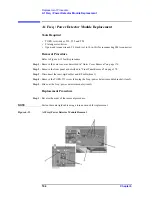
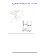
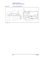
Refer to Figure 6-16 for this procedure.
Step 1.
Remove the outer cover as described in “Outer Cover Removal” on page 176.
Step 2.
Remove the front panel as described in “Front Panel Removal” on page 178.
Step 3.
Disconnect the semi-rigid cables (item 1).
Step 4.
Remove each two TORX T10 screws (item 2).
Step 5.
Slide out the Local Synthesize module (item 3).
Figure 6-16
A4/A5 Local Synthesize Module Removal
Replacement Procedure
Step 1.
Reverse the order of the removal procedure.
NOTE
Fasten the semi rigid cable using a torque wrench for replacement.
Summary of Contents for E5052A
Page 13: ...Contents 13 M 271 N 271 O 271 P 271 R 272 S 273 T 273 U 273 ...
Page 14: ...14 Contents ...
Page 22: ...22 Chapter1 General Information Required Equipment ...
Page 46: ...46 Chapter2 Performance Tests Individual Test Description Step 17 Turn off the power of AMP2 ...
Page 82: ...82 Chapter3 Adjustment Required Adjustment after Replacing Assembly ...
Page 218: ...216 Chapter6 Replacement Procedure A51 LCD Replacement Figure 6 27 A51 LCD Removal ...
Page 222: ...220 Chapter6 Replacement Procedure BNC Connector front Replacement ...
Page 244: ...242 AppendixB System Recovery Calibration of the Touch Screen ...
Page 250: ...248 AppendixC Firmware Update Firmware Update ...
Page 261: ...259 E Power Requirement E Power Requirement ...


