118
Chapter 4
Troubleshooting
Performance test failure troubleshooting
Performance test failure troubleshooting
This section describes the adjustment and troubleshooting procedures used when the
E5061A/E5062A fails the performance tests. If the performance of the instrument is
critical for the test limits and seems to be adjustable, perform first the adjustment(s) related
to the failed test. When the test result is far from the tolerance of the test or the
performance is not adjustable, isolate the faulty assembly in accordance with the
"Performance tests failure troubleshooting procedure".
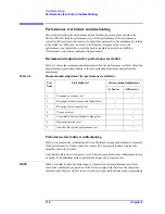
Recommended adjustment for performance test failure
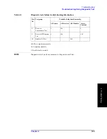
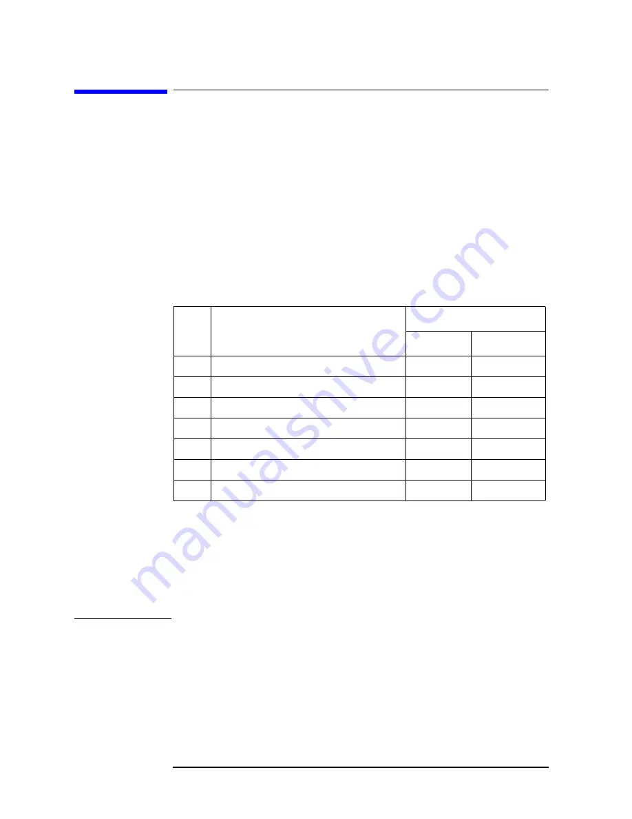
Table 4-5 shows the recommended adjustments when the performance test fails. Select the
adjustment program corresponding to the recommended adjustment and perform the
adjustment.
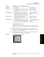
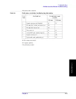
Performance test failure troubleshooting
Table 4-6 represents the relationships between the failed test and probable faulty assembly.
If the performance test failure cannot be removed by a proper adjustment, replace the
assembly shown in this table.
Note that this table lists some typical cases. There are possibilities that other assembly may
be faulty. To troubleshoot further, perform the diagnostic test procedures.
NOTE
When Crosstalk, System dynamic range or Uncorrected system performance test fails,
check first whether the connections of the RF semi-rigid cables between the suspicious
assembly and others are tight or loose. Also check for possible disconnection (impairment)
Table 4-5
Recommended adjustment for performance test failure
Test
Num.
First failed test
Recommended adjustment
A1 Source
A2 Receiver
1
Frequency accuracy test
2
RF output level accuracy and flatness test
3
RF output level linearity test
4
Trace noise test
5
Crosstalk & System Dynamic Range test
6
Dynamic accuracy test
7
Uncorrected system performance test
Summary of Contents for E5061A
Page 142: ...142 Chapter5 Replaceable Parts Replaceable Parts List Front Panel Figure 5 9 Front Panel ...
Page 168: ...168 Chapter6 Replacement Procedure Front Panel Removal Figure 6 2 Front Panel Removal ...
Page 192: ...192 Chapter6 Replacement Procedure A51 LCD Display Replacement Figure 6 16 A51 LCD Removal ...
Page 194: ...194 Chapter6 Replacement Procedure LCD Backlight Replacement ...
Page 198: ...198 Chapter7 Post Repair Procedures Post Repair Procedures ...
Page 202: ...202 AppendixA Manual Changes Manual Changes ...
Page 218: ...218 AppendixB System Recovery Calibration of the Touch Screen ...
Page 233: ...233 E Power Requirement E Power Requirement ...


