100
Chapter 4
Troubleshooting
Troubleshooting Using Diagnostic Test
Troubleshooting Using Diagnostic Test
The Agilent E5061A/E5062A has an diagnostic test function to diagnose the analog
measurement section and internal dc power supply voltages. The diagnostic test makes it
possible to isolate a faulty board assembly. The following paragraphs describe the
procedure to perform the diagnostic test.
Power On Self Test
Power-on self-test always takes place once the E5061A/E5062A is turned on. When a
failure is detected, a message "Power on self test failed" is displayed. The content of the
power-on self-test is the same as a part of the diagnostic test program and includes the dc
power supply voltage, source PLL synthesizer and level controller (ALC) tests. When the
self-test failed, perform the diagnostic test to break down into the individual tests and
narrow down failure possibilities.
NOTE
The following procedure can be used to restart the power-on self test as required.
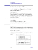
a. Press
key.
b. Click
Service Menu
and, then,
Test Menu
in the softkeys.
c. Click
Power On Test
to restart the test. Wait until the power-on test ends.
d. The test result (OK or Failed) is displayed in the
Power On Test
key.
PLL unlock
When a PLL of the frequency synthesizers is unlocked, not the "Power on self test failed"
but "Phase lock loop unlocked" message is displayed. If it occurs, A1 Source board may be
faulty.
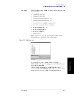
Contents of the diagnostic test
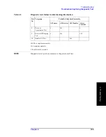
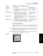
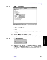
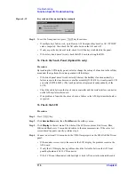
The diagnostic test contains 10 test groups shown in Table 4-1. Each test group can be
performed independently and verifies one of various operating characteristics of the analog
measurement section.
Table 4-1
Diagnostic test group menu
1
A1 Board DC-BUS Test
2
A2 Board DC-BUS Test
3
A1 Board Internal Level Monitor Test
4
A2 Board Internal Level Monitor Test
5
Source Power Accuracy (Step Attenuator) Test
6
Source Power linearity (Power sweep) Test
7
Receiver Absolute Gain Test
Summary of Contents for E5061A
Page 142: ...142 Chapter5 Replaceable Parts Replaceable Parts List Front Panel Figure 5 9 Front Panel ...
Page 168: ...168 Chapter6 Replacement Procedure Front Panel Removal Figure 6 2 Front Panel Removal ...
Page 192: ...192 Chapter6 Replacement Procedure A51 LCD Display Replacement Figure 6 16 A51 LCD Removal ...
Page 194: ...194 Chapter6 Replacement Procedure LCD Backlight Replacement ...
Page 198: ...198 Chapter7 Post Repair Procedures Post Repair Procedures ...
Page 202: ...202 AppendixA Manual Changes Manual Changes ...
Page 218: ...218 AppendixB System Recovery Calibration of the Touch Screen ...
Page 233: ...233 E Power Requirement E Power Requirement ...

