110
Chapter 4
Troubleshooting
Function Specific Troubleshooting
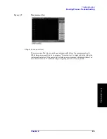
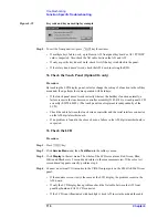
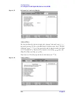
Figure 4-19
Key code and key name display example
Step 5.
To exit the front panel test, press
key three times.
•
If multiple keys fail to work, a problem in A22 front panel keyboard or A21 PCI DSP
card is suspected. Also check the flat cable between the A21 and A22.
•
If only a specific key doesn't work, check first if the key is subsided in the panel.
•
If the rotary knob doesn't work, check the A22 board involving the RPG.
To Check the Touch Panel (Option 016 only)
Procedure
By touching the LCD display panel, select or change the setting of a function in the softkey
menu and, then, perform the same operation with hardkeys.
•
If the touch panel doesn't work correctly whereas the hardkeys function normally, a
failure seems in the touch screen controller assembly (5183-4184) or touch-panel LCD
assembly (E5070-60102). (The touch panel is not replaceable independently of the
LCD.)
•
Check the cable between the touch screen controller and the serial interface connector
on the A20 digital motherboard.
•
If no problem is found in the above checks, a failure in the A20 digital motherboard is
suspected.
To Check the LCD
Procedure
Step 1.
Press
key.
Step 2.
Click
Service Menu
and, then,
Test Menu
in the softkeys menu.
Step 3.
Click
Display
in the test menu. The whole of the LCD screen turns Red, Green, Blue,
White and Black every 2 seconds and returns to the measurement view. If the color test
screen doesn't appear correctly, perform step 4.
Step 4.
Connect an external VGA monitor to the VIDEO output port on the E5061A/E5062A rear
panel.
•
If the monitor screen view is the same as the LCD display, the problem seems in the
A20 board.
•
If only the LCD display has a problem, check the flat cable between the A22 front
panel keyboard and A31 LCD connector.
•
If the LCD is not illuminated with backlight, check A52 inverter board and the cable
Summary of Contents for E5061A
Page 142: ...142 Chapter5 Replaceable Parts Replaceable Parts List Front Panel Figure 5 9 Front Panel ...
Page 168: ...168 Chapter6 Replacement Procedure Front Panel Removal Figure 6 2 Front Panel Removal ...
Page 192: ...192 Chapter6 Replacement Procedure A51 LCD Display Replacement Figure 6 16 A51 LCD Removal ...
Page 194: ...194 Chapter6 Replacement Procedure LCD Backlight Replacement ...
Page 198: ...198 Chapter7 Post Repair Procedures Post Repair Procedures ...
Page 202: ...202 AppendixA Manual Changes Manual Changes ...
Page 218: ...218 AppendixB System Recovery Calibration of the Touch Screen ...
Page 233: ...233 E Power Requirement E Power Requirement ...


