Chapter 6
167
Replacement Procedure
Front Panel Removal
6. Re
placem
ent Pro
c
e
d
u
re
Front Panel Removal
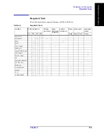
Tools required
•
TORX screwdriver T15 and T20
•
Flat edge screwdriver
Procedure
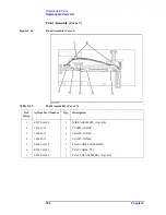
Refer to Figure 6-2 for this procedure.
Step 1.
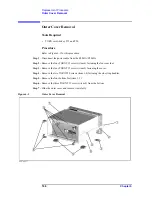
Remove the outer cover as described in “Outer Cover Removal” on page 166.
Step 2.
Release the cables from the cable clamp (item 1).
Step 3.
Remove the top trim (item 2) using a flat edge driver.
Step 4.
Remove the eight TORX T15 screws (item 3) fastening front panel.
Step 5.
Gradually push the front panel assembly towards the outside.
Step 6.
Release the mylar cable and flat cables from the cable clamps (item 6).
Step 7.
Disconnect the three cables (item 4, 5 and 8) from the front panel.
NOTE
Keep the mylar cable (item 7) connected.
The mylar cable and its connector are very fragile. It’s recommended to replace the mylar
cable when the cable is disconnected and connected frequently.
Summary of Contents for E5061A
Page 142: ...142 Chapter5 Replaceable Parts Replaceable Parts List Front Panel Figure 5 9 Front Panel ...
Page 168: ...168 Chapter6 Replacement Procedure Front Panel Removal Figure 6 2 Front Panel Removal ...
Page 192: ...192 Chapter6 Replacement Procedure A51 LCD Display Replacement Figure 6 16 A51 LCD Removal ...
Page 194: ...194 Chapter6 Replacement Procedure LCD Backlight Replacement ...
Page 198: ...198 Chapter7 Post Repair Procedures Post Repair Procedures ...
Page 202: ...202 AppendixA Manual Changes Manual Changes ...
Page 218: ...218 AppendixB System Recovery Calibration of the Touch Screen ...
Page 233: ...233 E Power Requirement E Power Requirement ...

