Chapter 2
31
Troubleshooting
Troubleshooting Using Diagnostic Test
2. T
ro
uble
shoo
tin
g
Test equipment required for diagnostic test
Table 2-2 shows the equipment required for performing the diagnostic test.
Table 2-2
Required equipment
Required test equipment
Qty
Recommended model
24 inch 50
Ω
cable
1
8120-8862, 8120-1839
To Execute the Diagnostic Test
To isolate faulty board assembly in analog section, execute the diagnostic test in
accordance with the following procedure. The test procedure needs to be performed using a
mouse and an external keyboard in addition to the front panel keys.
NOTE
To perform the diagnostic test properly, the following conditions must be met:
1. Environmental temperature: 23
°
C
±
5
°
C
NOTE
Do not operate front panel keys, keyboard and mouse during the diagnostic test. Changing
the instrument settings while the diagnostic test is in progress will cause incorrect test
results.
Step 1.
Connect a mouse and an external keyboard to the E5061B’s rear panel connector.
Step 2.
Press
key.
Step 3.
Press
Load Project
to select
Load Project
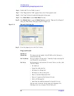
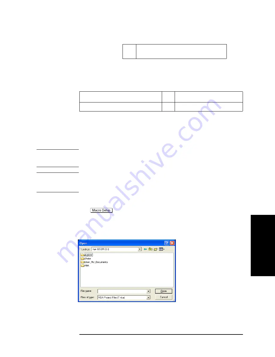
function."Open" dialog box will be displayed as
shown in Figure 2-13.
Figure 2-13
Open dialog box
Step 4.
Select "User [D]" (preset state) from menu in the "Look in:" box.
Step 5.
Double-click "Agilent" folder to open it and to access its menu.
8
Gain-Phase Absolute Measurement Test
(Option 3L5)
Table 2-1
Diagnostic test group menu
Summary of Contents for E5061B
Page 1: ... Established 1981 Advanced Test Equipment Rentals www atecorp com 800 404 ATEC 2832 ...
Page 51: ...50 Chapter3 Replaceable Parts Replaceable Parts List ...
Page 103: ...102 Chapter4 Replacement Procedure Handle Assembly Replacement ...
Page 116: ...115 E Power Requirement D Power Requirement ...
Page 123: ...122 AppendixE Messages ...


