96
Chapter 4
Replacement Procedure
LCD Assembly Replacement
LCD Assembly Replacement
Tools Required
•
torque screwdriver, T8, T10 and T20
•
torque screwdriver, T15 (set to 14 in-lb)
•
flat edge screwdriver
Removal Procedure
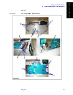
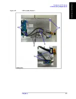
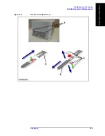
Refer to Figure 4-23 for this procedure.
Step 1.
Remove the Outer Cover as described in “Outer Cover Replacement” on page 54.
Step 2.
Remove the Front Panel as described in “Front Panel Replacement” on page 56.
Step 3.
Remove the Touch Screen Control Board as described in “Touch Screen Control Board
Replacement” on page 89.
Step 4.
Remove the Inverter Board as described in “Inverter Board Replacement” on page 90.
Step 5.
Disconnect the two connectors (item 1) of the cables.
Step 6.
Release the clamped cable from the clamp (item 2) on the LCD Assembly.
Step 7.
Remove the two cables (item 3) on the LCD Assembly.
Step 8.
Remove the four TORX T15 screws (item 4) fastening the LCD Assembly.
Step 9.
Lift the LCD Assembly carefully.
Replacement Procedure
Step 1.
Reverse the order of the removal procedure.
NOTE
Set a torque to 14 in-lb for torque driver when fasten the TORX T15 screws (item 4).
Summary of Contents for E5061B
Page 1: ... Established 1981 Advanced Test Equipment Rentals www atecorp com 800 404 ATEC 2832 ...
Page 51: ...50 Chapter3 Replaceable Parts Replaceable Parts List ...
Page 103: ...102 Chapter4 Replacement Procedure Handle Assembly Replacement ...
Page 116: ...115 E Power Requirement D Power Requirement ...
Page 123: ...122 AppendixE Messages ...


