background image

30

Chapter 2


Installation

Power Supply and Blown Fuses

Figure 2-10 

Power cable options

Summary of Contents for E5070A ENA Series

Page 1: ... Quick Start Guide Second Edition FIRMWARE REVISIONS SERIAL NUMBERS This manual applies directly to instruments that have the firmware revision 2 00 For additional information about firmware revisions see Appendix A Agilent Part No E5070 90011 April 2002 Printed in Japan ...

Page 2: ...pan Ltd Component Test PGU Kobe 1 3 2 Murotani Nishi ku Kobe Hyogo 651 2241 Japan Copyright Agilent Technologies Japan Ltd 2001 2002 Manual Printing History The manual s printing date and part number indicate its current edition The printing date changes when a new edition is printed minor corrections and updates that are incorporated at reprint do not cause the date to change The manual part numb...

Page 3: ...zard Keep Away from Live Circuits Operators must not remove instrument covers Component replacement and internal adjustments must be made by qualified maintenance personnel Do not replace components with the power cable connected Under certain conditions dangerous voltage levels may remain even after the power cable has been disconnected To avoid injuries always disconnect the power and discharge ...

Page 4: ... chassis which includes all exposed metal structure Stand by WARNING This warning sign denotes a hazard It calls attention to a procedure practice or condition that if not correctly performed or adhered to could result in injury or death to personnel CAUTION This Caution sign denotes a hazard It calls attention to a procedure practice or condition that if not correctly performed or adhered to coul...

Page 5: ... screen labeled Sample which can be selected executed by clicking menu button box or tab may be omitted key Indicates a hardkey key on the front panel or external keyboard labeled Sample key may be omitted Sample Indicates the hardkey whose key label is Sample Sample Item Indicates a series of key operations in which you press the Sample key make the item called Item on the displayed menu blink by...

Page 6: ...rogrammer s Guide Part Number E5070 900x2 attached to optional ABA This manual provides programming information for performing automatic measurement with the E5070A E5071A It includes an outline of remote control procedures for detecting measurement start trigger and end sweep end application programming examples command reference and related information VBA Programmer s Guide Part Number E5070 90...

Page 7: ...6 Connecting a Printer 27 Connecting the Ecal Module 28 Power Supply and Blown Fuses 29 Verification of the Power Supply 29 Verification and Connection of Power Cable 29 Blown Fuses 31 Starting the E5070A E5071A 31 Turning the Power ON and OFF 31 Disconnection from Supply Source 33 Setting the Internal Clock 33 Daily Maintenance 35 Cleaning Method 35 Maintaining an N type Connector on Each Port 35...

Page 8: ...8 Contents STEP 2 Calibration 49 STEP 3 Connecting the Device Under Test DUT 51 STEP 4 Analyzing Measurement Results 52 STEP 5 Outputting Measurement Results Save 55 A Manual Changes Manual Changes 58 ...

Page 9: ...oduction of This Manual This chapter provides an overview of this manual to use this manual efficiently and describes the features of the Agilent E5070A E5071A briefly See this manual first when you use the E5070A E5071A for the first time ...

Page 10: ...his Manual This chapter provides an overview of this manual to use this manual efficiently and describes the features of the Agilent E5070A E5071A briefly See this manual first when you use the E5070A E5071A for the first time o Chapter 2 Installation This chapter provides information about how to set up the Agilent E5070A E5071A RF network analyzer and about daily maintenance o Chapter 3 Quick St...

Page 11: ...aneously measuring all the built in test ports realizes high speed measurement while executing full port calibration removes error factors thoroughly to achieve high accuracy measurement 3 The built in balanced measurement function matching circuit simulation function and port impedance transformation function enables you to correctly evaluate RF balanced devices such as balanced SAW filters 4 The...

Page 12: ...12 Chapter1 Introduction of This Manual Overview of the E5070A E5071A ...

Page 13: ...13 2 Installation 2 Installation This chapter provides information about how to set up the Agilent E5070A E5071A RF network analyzer and about daily maintenance ...

Page 14: ...and how to install the flanges needed to install it in a rack o Connecting the Accessories on page 24 Provides information for connecting the mouse keyboard BNC cable and Ecal module to the E5070A E5071A o Power Supply and Blown Fuses on page 29 Shows how to check the power supply as well as check and connect the power cable This section also describes what to do for a blown fuse o Starting the E5...

Page 15: ...h the analyzer for any damage or defects Step 3 By referring to Table 2 1 and Figure 2 1 check that all packaged items supplied with the analyzer have been provided as per the specified options Step 4 After checking if one of the following applies contact your nearest Agilent Technologies sales and service office 1 The packing box or shock absorbing material used to package the analyzer has been d...

Page 16: ...of the manual or sample program disk is a number that is incremented each time a revision is made with 0 regarded as the first edition The network analyzer will always be supplied with the latest versions of these items Userís Guide E5070 900x0 1 Installation and Quick Start Guide E5070 900x1 1 Programmerís Guide E5070 900x2 1 VBA Programmerís Guide E5070 900x3 1 CD ROM of the manual 6 6 The CD RO...

Page 17: ...Chapter 2 17 Installation Checking the Shipment 2 Installation Figure 2 1 E5070A E5071A Accessories ...

Page 18: ...ing requirements NOTE Above environmental requirements are NOT for the specifications and measurement accuracy of the analyzer but for the operating environment of the analyzer Temperature 5 C to 40 C Temperature range at the error correction 23 C 5 C 1 C deviation from the temperature when performing the error correction Humidity 90 at 40 C non condensation Altitude 0 to 2 000 m 0 to 6 561 feet V...

Page 19: ...ations and measurement accuracy of the analyzer see Specifications And Supplemental Information in the E5070A E5071A User s Guide When the environmental temperature around the analyzer is kept within the temperature range of the operating environment specification See Section Operating Environments on page 18 the analyzer conforms to the requirements of the safety standard Furthermore under that t...

Page 20: ...n of Power Cable in Case of Emergency As described in Disconnection from Supply Source on page 33 the power supply is disconnected by removing the power cable s connector plug from either the AC outlet or the E5070A E5071A unit When installing the E5070A E5071A ensure that there is sufficient free space around the unit to permit quick disconnection of the plug from AC outlet or E5070A E5071A unit ...

Page 21: ...nalyzer in an equipment rack as part of a measurement system Option 1CM without the handles Option 1CP with the handles Table 2 3 Agilent E5070A E5071A handles rack mounting options Option Name Agilent Part Number 1CN Handle Kit 5063 9229 1CM Rack mount Kit 5063 9216 1CP Rack mount and Handle Kit 5063 9223 Table 2 4 Contents of each option Option Contents Quantity 1CN Front Handles 2 Screws 6 Trim...

Page 22: ...hesive backed trim strip 1 from each side of the outer frame of the E5070A E5071A front panel Step 2 Use the provided screws to mount the front handles 2 on each side of the E5070A E5071A front panel frame Step 3 Attach the provided modified trim strip 3 to each front handle in order to cover the front panel locking screws WARNING If the installed front handle becomes damaged replace it with a new...

Page 23: ...of the E5070A E5071A lift the bar marked TAB on the inner side of the foot and slide the foot toward the bar Step 4 Mount the E5070A E5071A on the rack How to Install the Rack mount and Handle Kit Option 1CP The rack mount and handle kit includes both the rack mounting flanges locking side plates and front handles While referring to Figure 2 4 install the rack mount kit by following these steps St...

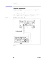
Page 24: ... of accessories using the USB ports on the front panel or each of the ports on the rear panel Connecting the Mouse and Keyboard As shown in Figure 2 5 connect the supplied mouse and keyboard to the mini DIN mouse port and mini DIN keyboard port respectively before turning ON the power Figure 2 5 Connecting the mouse and keyboard ...

Page 25: ...h Option 1E5 high stability frequency standard connect the BNC cable from the Ref Oven terminal to the Ref In terminal on the rear panel as shown in Figure 2 6 The BNC cable is included in Option 1E5 When Option 1E5 is installed the frequency accuracy and stability of the E5070A E5071A will further improve Figure 2 6 Connecting the BNC cable ...

Page 26: ... Guide set the E5070A E5071A LAN Step 2 As shown in Figure 2 7 connect a LAN cable to the LAN port on the rear panel of the E5070A E5071A Figure 2 7 Connecting the LAN cable NOTE When connecting the E5070A E5071A to a LAN for use consult the network administrator about proper LAN settings Do not connect a LAN cable until the proper LAN settings have been completed Connecting the E5070A E5071A to a...

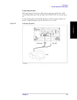
Page 27: ...available printer to the printer parallel port or USB Universal Serial Bus port on the rear panel of the E5070A E5071A as shown in Figure 2 8 For the available printers of the E5070A E5071A in its factory shipped condition see Section Compatible Printers in the E5070A E5071A User s Guide Figure 2 8 Connecting the printer ...

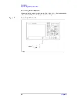
Page 28: ... the Accessories Connecting the Ecal Module When using the Ecal module connect one end of the USB cable to the Ecal module and the other end to the USB port on the front panel as shown in Figure 2 9 Figure 2 9 Connecting the ECal module ...

Page 29: ...rom the power outlet Step 1 Confirm that the power cable is not damaged WARNING NEVER use a power cable showing any sign of damage Faulty cables can cause electrical shock Step 2 Use the supplied cable to connect between the power cable receptacle Figure 2 11 on page 32 on the rear panel of the E5070A E5071A and a three wire power outlet with the grounding prong firmly connected in the ground slot...

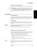
Page 30: ...30 Chapter2 Installation Power Supply and Blown Fuses Figure 2 10 Power cable options ...

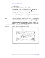
Page 31: ...angerous electrical shock Starting the E5070A E5071A This section describes how to turn on off the E5070A E5071A power how to cut off the power supply in an emergency and how to set the internal clock Turning the Power ON and OFF Perform the following steps to turn the power ON or OFF Turning the Power ON Step 1 If the standby switch in the lower left part of the front panel is in the depressed po...

Page 32: ... turning the power off and the power will turn OFF after a few seconds NOTE Under normal circumstances always press the standby switch or send the shutdown command from an external controller to execute the E5070A E5071A shutdown process Never cut off the power supply directly by disconnecting the power cable plug from the rear panel of the unit If the power supply is cut off directly by disconnec...

Page 33: ...low the methods described in Turning the Power OFF on page 32 Setting the Internal Clock You can set the date time displayed at the lower right of the screen When you save data in the storage unit for example the internal clock data will be used The following describes the setting procedure that uses keys on the front panel NOTE When turning on the instrument power for the first time after deliver...

Page 34: ... daylight saving changes box becomes selectable To set the function of automatically making summertime adjustment to ON turn the rotary knob to point the focus to the Automatically adjust clock for daylight saving changes box and press the rotary knob to display the Ö mark Figure 2 13 Step 4 Turn the rotary knob on the front panel to point the focus to the Time Zone tab and press the key to move t...

Page 35: ...ly with a dry cloth or soft cloth dampened with water and wrung dry Never attempt to clean the inside of the instrument WARNING To avoid an electric shock always disconnect the power cord of the E5070A E5071A from the power outlet when cleaning To clean a touch screen type LCD Option 016 do not wet the cloth with water Maintaining an N type Connector on Each Port Each port on the front panel of th...

Page 36: ...Agilent Technologies Service Center by seeing Section Considerations When Shipping to a Service Center Due to Breakdown or Other Problem on page 36 Considerations When Shipping to a Service Center Due to Breakdown or Other Problem When shipping the E5070A E5071A to an Agilent Technologies Service Center because of breakdown or other problem for shipment use the packing box and shock absorbing mate...

Page 37: ...parts on the front panel and display area of the Agilent E5070 E5071A RF Network Analyzer Using the example of measuring a bandpass filter you will quickly learn how to easily operate the E5070 E5071A by understanding the basic measurement procedures and operation of the E5070 E5071A ...

Page 38: ...hree methods of operation keys mouse and touch panel Basic Measurement Procedures on page 47 Describes the basic measurement procedures for using the E5070 E5071A Measurement Example of a Bandpass Filter on page 48 Illustrates the basic measurement method for the E5070 E5071A through an example of the transmission measurement of a bandpass filter ...

Page 39: ... of the E5070 E5071A parts on the front panel and display area For more information see Chapter 2 Overview of Functions in theE5070 E5071A User s Guide This section also describes three operation methods using the keys mouse and touch panel Option 016 Front Panel The names and short descriptions of the E5070 E5071A parts on the front panel are as shown as follows Figure 3 1 Front Panel ...

Page 40: ...IMULUS Block see Chapter 2 Overview of Functions in the E5070 E5071A User s Guide 6 Floppy Disk Drive Stores installs from to the E5070 E5071A the files containing the instrument setting conditions of the E5070 E5071A measurement data the VBA Visual Basic for Applications program etc Compatible with 3 5 inch 1 44 MB DOS Disk Operating System formatted floppy disks 7 NAVIGATION Block A group of key...

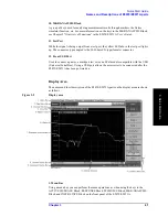
Page 41: ...p The connector type adopted is the 50 W based N type female connector 12 Front USB Port Used to connect a printer a multiport test set or an ECal module compatible with the USB Universal Serial Bus Using a USB port allows the accessories to be connected after the E5070 E5071A has been powered on Display Area The names and short description of the E5070 E5071A parts on the display area are shown a...

Page 42: ...is displayed instead of the marker number and indicates the marker value of the reference marker When the reference marker is set ON the stimulus value and response value of other markers indicate the differences from the values of the reference marker 8 Reference Line Indicator Displays the position of the reference line 9 Marker Used for reading out values on a trace Using a marker makes it easy...

Page 43: ...e front panel using a mouse and keyboard and using a touch screen Option 016 This section illustrates these three operating methods through the example in which the channel window layout is set to the four channel display as shown in Figure 3 3 In the next section and those following it a series of operations is expressed as follows Display Allocate Channels Figure 3 3 Four Channel Display ...

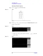
Page 44: ... Keys Step 1 Press the key in the RESPONSE Block Figure 3 4 Step 1 Step 2 Press the or the key to move the cursor to the Allocate Channels button then press the or the key Figure 3 5 Step 2 Press the or the key to move the cursor to the button then press the key Figure 3 6 Step 3 ...

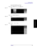
Page 45: ...ods of Operation 3 Quick Start Guide Operation Method Using a Mouse Step 1 From the Response menu click the Display button Figure 3 7 Step 1 Step 2 Click the Allocate Channels button Figure 3 8 Step 2 Step 3 Click the button Figure 3 9 Step 3 ...

Page 46: ...ation Operation Method Using the Touch Screen Option 016 Step 1 Press the Display button after presetting the E5070 E5071A Executing key Figure 3 10 Step 1 Step 2 Press the Allocate Channels button Figure 3 11 Step 2 Press the button Figure 3 12 Step 3 ...

Page 47: ...cting the S parameter o Selecting the data format o Specifying the frequency range o Specifying the number of measurement points o Specifying the power level o Specifying the IF bandwidth STEP 2 Calibration o Specifying the calibration kit o Selecting the calibration type o Measuring the calibration data o Making the error correction ON o Saving the calibration data STEP 3 Connecting the device un...

Page 48: ...nsmission characteristics set the S parameter to S12 Step 3 Set the data format to the log magnitude format Format Log Mag Step 4 Set the center frequency to the bandpass filter center frequency Next specify the span frequency which is set to 200 MHz in this measurement example Center 9 4 7 5 M m Span 2 0 0 M m NOTE When entering the frequency unit using the keyboard type G for GHz M for MHz and k...

Page 49: ...ibration using the test port 1 and 2 Cal Calibration 2 Port Cal Select Ports 1 2 Step 3 Connect the OPEN standard included in the calibration kit to the other end of the measurement cable that is connected to the test port 1 as shown in Figure 3 13 and measure the open calibration data at the test port 1 After measuring the open calibration data symbol Ö is displayed to the left of the Port 1 Open...

Page 50: ...alibration measurement DONE The calibration factor is calculated based on the calibration data acquired and the error correction is turned ON Cal Calibration 2 Port Cal Done Step 7 Select the type in which the data is to be saved before saving the calibration factor calculated based on the calibration data Save Recall Save Type State Cal Step 8 Store the calibration file to the disk of the E5070 E...

Page 51: ... the setting value for the power level 10 dBm may destroy some DUTs Should this occur first select the proper power level and then connect the DUT to the E5070 E5071A Step 2 Set the appropriate scale by executing the auto scale See Figure 3 16 Scale Auto Scale You can also adjust the scale by entering arbitrary values in the Scale Div button Reference Position button and Reference Value Figure 3 1...

Page 52: ...B bandwidth Measuring the Insertion Loss Step 1 Display a marker Marker Marker 1 Step 2 Using one of the following methods move the marker to the center frequency of the bandpass filter On the entry bar press 9 4 7 5 M m Turn the rotary knob on the front panel to set it to the center frequency 947 5 MHz Step 3 Read the marker value displayed as shown in Figure 3 17 In this example the response val...

Page 53: ...enter frequency 947 5 MHz Step 3 Specify the bandwidth definition value that defines the pass band of the filter In this measurement example it is set to 3 dB Marker Search Bandwidth Value 3 x 1 Step 4 Set the bandwidth search function ON Marker Search Bandwidth Step 5 The bandwidth data items BW cent low high Q loss will be displayed See Figure 3 18 Table 3 1 Parameters for the Bandwidth Search F...

Page 54: ...54 Chapter3 Quick Start Guide Measurement Example of a Bandpass Filter Figure 3 18 Measuring the 3 dB Bandwidth ...

Page 55: ...d is a text file you can analyze the data using Microsoft Excel Step 1 Follow the operation method described below to save the trace data Save Recall Save Trace Data Saving the Display Screen You can save the screen displayed on the E5070 E5071A to the disk of the E5070 E5071A in Windows bitmap file format extension bmp or Portable Network Graphics format extension png Step 1 Follow the operation ...

Page 56: ...56 Chapter3 Quick Start Guide Measurement Example of a Bandpass Filter ...

Page 57: ... Changes A Manual Changes This appendix contains the information required to adapt this manual to versions or configurations of the E5070A E5071A manufactured earlier than the current printing date of this manual ...

Page 58: ... ten character serial number that is stamped on the serial number plate Figure A 1 The first five characters are the serial prefix and the last five digits are the suffix Figure A 1 Example of Serial Number Plate Table A 1 Manual Changes by Serial Number Serial Prefix or Number Make Manual Changes Table A 2 Manual Changes by Firmware Version Version Make Manual Changes ...

Page 59: ...escriptions of the LCD screen 41 saving the display screen 55 turning the date time display ON and OFF 35 Displays 42 DUT connecting the DUT 51 E E5070A E5071A basic measurement procedures 47 items packaged with the E5070A E5071A 16 overview of the E5070A E5071A 11 starting the E5070A E5071A 31 three methods of operation 43 Ecal module connecting the Ecal module 28 ENTRY block 40 environmental req...

Page 60: ...lown fuse 31 presetting the E5070A E5071A 48 printer connecting the printer 27 product overview of the E5070A E5071A 11 Programmer s Guide 6 Q Q bandwidth search function 53 Quick Start Guide 6 contents 10 R rack mount and handle kit how to install the rack mount and handle kit 23 rack mount kit how to install the rack mount kit 23 reference line indicator 42 RESPONSE block 40 S safety symbols 4 s...

Page 61: ...Index 61 Index U USB port front panel 41 User s Guide 6 V VBA Programmer s Guide 6 ...

Page 62: ......

Page 63: ...rope Agilent Technologies Test Measurement European Marketing Organization P O Box 999 1180 AZ Amstelveen The Netherlands tel 31 20 547 9999 Japan Agilent Technologies Japan Ltd Call Center 9 1 Takakura Cho Hachioji Shi Tokyo 192 8510 Japan tel 81 426 56 7832 fax 81 426 56 7840 Latin America Agilent Technologies Latin American Region Headquarters 5200 Blue Lagoon Drive Suite 950 Miami Florida 3312...

Reviews: