40
Chapter 3
Quick Start Guide
Names and Descriptions of E5070/E5071A parts
1. Standby Switch
Allows the switch between power-on (|) and standby mode (
) on the E5070/E5071A.
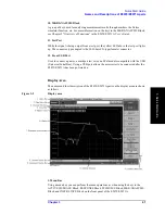
2. LCD Screen
Displays measurement traces, instrument setting conditions, menu bars, the Visual Basic
Editor, etc. Consists of a 10.4-inch TFT color LCD. For details on the information
displayed on the LCD screen, see “Display Area” on page 41.
3. ACTIVE CH/TRACE Block
A group of keys used for selecting the active channel and an active trace. For more
information on the functions of the keys in the ACTIVE CH/TRACE Block, see Chapter 2
“Overview of Functions” in the E5070/E5071A
User’s Guide
.
4. RESPONSE Block
A group of keys used for the selection of a measurement parameters/data formats ,
displaying, calibration, etc. For more information on the functions of the keys in the
RESPONSE Block, see Chapter 2 “Overview of Functions” in theE5070/E5071A
User’s
Guide
.
5. STIMULUS Block
A group of keys used for specifying the setup for signal sources, trigger, etc. For more
information on the keys in the STIMULUS Block, see Chapter 2 “Overview of Functions”
in the E5070/E5071A
User’s Guide
.
6. Floppy Disk Drive
Stores/installs from/to the E5070/E5071A the files containing the instrument setting
conditions of the E5070/E5071A, measurement data, the VBA (Visual Basic for
Applications) program, etc. Compatible with 3.5-inch, 1.44 MB, DOS (Disk Operating
System) formatted floppy disks.
7. NAVIGATION Block
A group of keys used for the movement/selection of the focus in menu bars/softkey menu
bar/dialog boxes and for manipulating markers. For the functions of the keys in the
NAVIGATION Block, see Chapter 2 “Overview of Functions” in the E5070/E5071A
User’s Guide
.
8. ENTRY Block
A group of keys used for entering numeric data on the E5070/E5071A settings. For more
information on the functions of the keys in the ENTRY Block, see Chapter 2 “Overview of
Functions” in the E5070/E5071A
User’s Guide
.
9. INSTR STATE Block
A group of keys used for specifying the setup for controlling and managing the
E5070/E5071A such as executing the limit test function, printing measurement results,
executing VBA macros, and presetting (initializing) the E5070/E5071A. For more
information on the keys in the INSTR STATE Block, see Chapter 2 “Overview of
Functions” in the E5070/E5071A
User’s Guide
.
Summary of Contents for E5070A ENA Series
Page 12: ...12 Chapter1 Introduction of This Manual Overview of the E5070A E5071A ...
Page 30: ...30 Chapter2 Installation Power Supply and Blown Fuses Figure 2 10 Power cable options ...
Page 56: ...56 Chapter3 Quick Start Guide Measurement Example of a Bandpass Filter ...
Page 61: ...Index 61 Index U USB port front panel 41 User s Guide 6 V VBA Programmer s Guide 6 ...
Page 62: ......


