Chapter 3
51
Quick Start Guide
Measurement Example of a Bandpass Filter
3.
Qu
ick S
tar
t G
u
id
e
STEP 3. Connecting the Device Under Test(DUT)
Step 1.
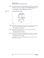
Connect t the DUT to the E5070/E5071A. (See Figure 3-15.)
Figure 3-15
Connecting the DUT
NOTE
Applying the setting value for the power level (-10 dBm) may destroy some DUTs. Should
this occur, first select the proper power level and then connect the DUT to the
E5070/E5071A.
Step 2.
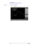
Set the appropriate scale by executing the auto scale. (See Figure 3-16.)
•
[Scale] - Auto Scale
You can also adjust the scale by entering arbitrary values in the
Scale/Div
button,
Reference Position
button, and
Reference Value
.
Figure 3-16
S21 trace after executing the auto scale
Summary of Contents for E5070A ENA Series
Page 12: ...12 Chapter1 Introduction of This Manual Overview of the E5070A E5071A ...
Page 30: ...30 Chapter2 Installation Power Supply and Blown Fuses Figure 2 10 Power cable options ...
Page 56: ...56 Chapter3 Quick Start Guide Measurement Example of a Bandpass Filter ...
Page 61: ...Index 61 Index U USB port front panel 41 User s Guide 6 V VBA Programmer s Guide 6 ...
Page 62: ......


