background image

63

A. Ma

nu
al 
Ch
an
ges

A

Manual Changes

This appendix contains the information required to adapt this manual to versions or 
configurations of the E5070B/E5071B manufactured earlier than the current printing date 
of this manual.

Summary of Contents for E5070B ENA Series

Page 1: ... E5071B ENA Series RF Network Analyzers Installation and Quick Start Guide Seventh Edition Manufacturing No E5070 90081 November 2007 Advanced Test Equipment Rentals www atecorp com 800 404 ATEC 2832 Established 1981 ...

Page 2: ...07 Agilent Technologies Manual Printing History The manual s printing date and part number indicate its current edition The printing date changes when a new edition is printed minor corrections and updates that are incorporated at reprint do not cause the date to change The manual part number changes when extensive technical changes are incorporated August 2002 First Edition part number E5070 9003...

Page 3: ...nflammable gasses or fumes Operation of any electrical instrument in such an environment clearly constitutes a safety hazard Keep Away from Live Circuits Operators must not remove instrument covers Component replacement and internal adjustments must be made by qualified maintenance personnel Do not replace components with the power cable connected Under certain conditions dangerous voltage levels ...

Page 4: ...In position of push button switch Out position of push button switch A chassis terminal a connection to the instrument s chassis which includes all exposed metal structure Stand by WARNING This warning sign denotes a hazard It calls attention to a procedure practice or condition that if not correctly performed or adhered to could result in injury or death to personnel CAUTION This Caution sign den...

Page 5: ...to the implied warranties of merchantability and fitness for a particular purpose Agilent shall not be liable for errors or for incidental or consequential damages in connection with the furnishing use or performance of this document or any information contained herein Should Agilent and the user have a separate written agreement with warranty terms covering the material in this document that conf...

Page 6: ... screen labeled Sample which can be selected executed by clicking menu button box or tab may be omitted key Indicates a hardkey key on the front panel or external keyboard labeled Sample key may be omitted Sample Indicates the hardkey whose key label is Sample Sample Item Indicates a series of key operations in which you press the Sample key make the item called Item on the displayed menu blink by...

Page 7: ...rogrammer s Guide Part Number E5070 900x2 attached to optional ABA This manual provides programming information for performing automatic measurement with the E5070B E5071B It includes an outline of remote control procedures for detecting measurement start trigger and end sweep end application programming examples command reference and related information VBA Programmer s Guide Part Number E5070 90...

Page 8: ...8 ...

Page 9: ...necting a Printer 29 Connecting the Ecal Module 30 Power Supply and Blown Fuses 31 Verification of the Power Supply 31 Verification and Connection of Power Cable 31 Blown Fuses 33 Starting the E5070B E5071B 34 Turning the Power ON and OFF 34 Disconnection from Supply Source 35 Setting the Internal Clock 36 Setting the Date Time 36 Turning the Date Time Display ON and OFF 37 Initial Registration of...

Page 10: ...ss Filter 54 STEP 1 Determining Measurement Conditions 54 STEP 2 Calibration 55 STEP 3 Connecting the Device Under Test DUT 57 STEP 4 Analyzing Measurement Results 58 STEP 5 Outputting Measurement Results Save 61 A Manual Changes Manual Changes 64 Change 2 64 Change 1 64 ...

Page 11: ...roduction of This Manual This chapter provides an overview of this manual to use this manual efficiently and describes the features of the Agilent E5070B E5071B briefly See this manual first when you use the E5070B E5071B for the first time ...

Page 12: ...lent E5070B E5071B briefly See this manual first when you use the E5070B E5071B for the first time R Chapter 2 Installation This chapter provides information about how to set up the Agilent E5070B E5071B RF network analyzer and about daily maintenance R Chapter 3 Quick Start Guide This chapter describes the functions of parts on the front panel and display area of the Agilent E5070B E5071B RF Netw...

Page 13: ...ltaneously measuring all the built in test ports realizes high speed measurement while executing full port calibration removes error factors thoroughly to achieve high accuracy measurement 3 The built in balanced measurement function matching circuit simulation function and port impedance transformation function enables you to correctly evaluate RF balanced devices such as balanced SAW filters 4 T...

Page 14: ...14 Chapter1 Introduction of This Manual Overview of the E5070B E5071B ...

Page 15: ...15 2 Installation 2 Installation This chapter provides information about how to set up the Agilent E5070B E5071B RF network analyzer and about daily maintenance ...

Page 16: ...nd how to install the flanges needed to install it in a rack R Connecting the Accessories on page 26 Provides information for connecting the mouse keyboard BNC adaptor and Ecal module to the E5070B E5071B R Power Supply and Blown Fuses on page 31 Shows how to check the power supply as well as check and connect the power cable This section also describes what to do for a blown fuse R Starting the E...

Page 17: ...h the analyzer for any damage or defects Step 3 By referring to Table 2 1 and Figure 2 1 check that all packaged items supplied with the analyzer have been provided as per the specified options Step 4 After checking if one of the following applies contact your nearest Agilent Technologies sales and service office 1 The packing box or shock absorbing material used to package the analyzer has been d...

Page 18: ...ions of these items E5070 905xx 1 R CD ROM of the Agilent IO Libraries Suite E2094 60003 1 R System recovery disk E5070 16000 1 R GPIB adapter 4 4 Use this adapter when a GPIB cable is connected to the rear panel GPIB connector E2078 62101 1 Options R Keyboard Option 810 1 R Mouse Option 820 1 R Manual Option ABA 5 5 The x in the part number of the Manual or sample program disk is a number that is...

Page 19: ...Chapter 2 19 Installation Checking the Shipment 2 Installation Figure 2 1 E5070B E5071B Accessories ...

Page 20: ...nts NOTE Above environmental requirements are NOT for the specifications and measurement accuracy of the analyzer but for the operating environment of the analyzer Temperature 5 C to 40 C Temperature range at the error correction 23 C 5 C 1 C deviation from the temperature when performing the error correction Humidity 20 to 80 at wet bulb temperature 29 C non condensation Altitude 0 to 2 000 m 0 t...

Page 21: ...ations and measurement accuracy of the analyzer see Specifications And Supplemental Information in the E5070B E5071B User s Guide When the environmental temperature around the analyzer is kept within the temperature range of the operating environment specification See Section Operating Environments on page 20 the analyzer conforms to the requirements of the safety standard Furthermore under that t...

Page 22: ...ample of the static safe work station Ensuring Adequate Free Space around Analyzer for Immediate Disconnection of Power Cable in Case of Emergency As described in Disconnection from Supply Source on page 35 the power supply is disconnected by removing the power cable s connector plug from either the AC outlet or the E5070B E5071B unit When installing the E5070B E5071B ensure that there is sufficie...

Page 23: ...nalyzer in an equipment rack as part of a measurement system Option 1CM without the handles Option 1CP with the handles Table 2 2 Agilent E5070B E5071B handles rack mounting options Option Name Agilent Part Number 1CN Handle Kit 5063 9229 1CM Rack mount Kit 5063 9216 1CP Rack mount and Handle Kit 5188 4430 Table 2 3 Contents of each option Option Contents Quantity 1CN Front Handles 2 Screws 6 Trim...

Page 24: ...hesive backed trim strip 1 from each side of the outer frame of the E5070B E5071B front panel Step 2 Use the provided screws to mount the front handles 2 on each side of the E5070B E5071B front panel frame Step 3 Attach the provided modified trim strip 3 to each front handle in order to cover the front panel locking screws WARNING If the installed front handle becomes damaged replace it with a new...

Page 25: ...tep 4 Mount the E5070B E5071B on the rack How to Install the Rack mount and Handle Kit Option 1CP The rack mount and handle kit includes both the rack mounting flanges locking side plates and front handles While referring to Figure 2 4 install the rack mount kit by following these steps Step 1 Remove the adhesive backed trim strip 1 from each side of the outer frame of the E5070B E5071B front pane...

Page 26: ...iety of accessories using the USB ports on the front panel or each of the ports on the rear panel Connecting the Mouse and Keyboard As shown in Figure 2 5 connect the mouse and keyboard to the mini DIN mouse port and mini DIN keyboard port respectively before turning ON the power Figure 2 5 Connecting the mouse and keyboard ...

Page 27: ...Option 1E5 high stability frequency standard connect the BNC adaptor from the Ref Oven terminal to the Ref In terminal on the rear panel as shown in Figure 2 6 The BNC adaptor is included in Option 1E5 When Option 1E5 is installed the frequency accuracy and stability of the E5070B E5071B will further improve Figure 2 6 Connecting the BNC adaptor ...

Page 28: ... Guide set the E5070B E5071B LAN Step 2 As shown in Figure 2 7 connect a LAN cable to the LAN port on the rear panel of the E5070B E5071B Figure 2 7 Connecting the LAN cable NOTE When connecting the E5070B E5071B to a LAN for use consult the network administrator about proper LAN settings Do not connect a LAN cable until the proper LAN settings have been completed Connecting the E5070B E5071B to a...

Page 29: ...available printer to the printer parallel port or USB Universal Serial Bus port on the rear panel of the E5070B E5071B as shown in Figure 2 8 For the available printers of the E5070B E5071B in its factory shipped condition see Section Compatible Printers in the E5070B E5071B User s Guide Figure 2 8 Connecting the printer ...

Page 30: ... the Accessories Connecting the Ecal Module When using the Ecal module connect one end of the USB cable to the Ecal module and the other end to the USB port on the front panel as shown in Figure 2 9 Figure 2 9 Connecting the ECal module ...

Page 31: ...rom the power outlet Step 1 Confirm that the power cable is not damaged WARNING NEVER use a power cable showing any sign of damage Faulty cables can cause electrical shock Step 2 Use the supplied cable to connect between the power cable receptacle Figure 2 11 on page 35 on the rear panel of the E5070B E5071B and a three wire power outlet with the grounding prong firmly connected in the ground slot...

Page 32: ...32 Chapter2 Installation Power Supply and Blown Fuses Figure 2 10 Power cable options ...

Page 33: ...must be repaired Ship the E5070B E5071B to the nearest Agilent Technologies Service Center by seeing Section Considerations When Shipping to a Service Center Due to Breakdown or Other Problem on page 42 The E5070B E5071B uses the following fuse type UL CSA Type Slow Blo 6 3 A 250 Vac WARNING Do NOT replace the fuse yourself doing this may expose you to dangerous electrical shock ...

Page 34: ...Turning the Power OFF Step 1 Use either of the following methods to turn the power OFF Press the standby switch in the lower left part of the front panel now in the pressed down position to put it in the popped up position Send the shutdown command from an external controller These operations will start the E5070B E5071B shutdown process required software and hardware processes for turning the pow...

Page 35: ...n it is necessary to disconnect the power supply in order to avoid shock hazards etc pull out the power cable plug from either the AC outlet side or the E5070B E5071B side NOTE To allow this operation to be performed smoothly be sure to follow the guidelines in Ensuring Adequate Free Space around Analyzer for Immediate Disconnection of Power Cable in Case of Emergency on page 22 When turning the p...

Page 36: ...internal clock Setting the Date Time Step 1 Press the System key in the INSTR STATE block Press the or key to move the focus to the Misc Setup button and then press the Enter or key Press the or key to move the focus to the Clock Setup button and then press the Enter or key Point the focus to the Set Date and Time button and press the Enter key The Date Time Properties dialog box will appear Figur...

Page 37: ... knob on the front panel to point the focus to the Time Zone tab and press the key to move the focus to the Date Time tab Step 5 By referring to Figure 2 12 turn the rotary knob on the front panel to point the focus to the desired item Press the or key to set each item Step 6 Turn the rotary knob on the front panel to point the focus to the OK button and then press Enter key Turning the Date Time ...

Page 38: ...he initial registration of the E5070B E5071B therefore connect the mouse and the keyboard before turning on the power NOTE If you perform the following procedure incorrectly a message asking you whether to return to the previous registration screen and perform the registration appears In this case follow the instruction to return to the previous registration screen Step 1 Turns on the E5070B E5071...

Page 39: ...log box select the I accept this agreement box and click the Next button Figure 2 15 Then the Windows 2000 operating system is restarted automatically Figure 2 15 Windows 2000 Professional Setup dialog box Step 4 The Network Identification wizard appears Click the Next button Figure 2 16 Figure 2 16 Network Identification wizard ...

Page 40: ... that agena is in the User Name box If not type in agena Finally click the Next button Figure 2 17 Figure 2 17 Network Identification Wizard dialog box 1 2 Step 6 In the Network Identification Wizard dialog box 2 2 click the Finish button to finish the initial registration of the E5070B E5071B Figure 2 17 Then the measurement display of theE5070B E5071B appears Figure 2 18 Network Identification W...

Page 41: ...rt on the front panel of the E5070B E5071B has an N type connector female In the RF band soil or damage on the connector or cable will affect the measurements The following describes how to handle and maintain these N type connectors The connectors should always be kept clean and away from dirt To prevent the electrostatic discharge ESD do not touch the contact face of the connector Never attempt ...

Page 42: ...down or other problem for shipment use the packing box and shock absorbing material used to package the analyzer or static protective package that replaces them For your nearest Agilent Technologies Service Center contact the Agilent Technologies Customer Center shown at the end of the Manual NOTE Occasionally a few pixels may appear on the screen as a fixed point of blue green or red Please note ...

Page 43: ...arts on the front panel and display area of the Agilent E5070B E5071B RF Network Analyzer Using the example of measuring a bandpass filter you will quickly learn how to easily operate the E5070B E5071B by understanding the basic measurement procedures and operation of the E5070B E5071B ...

Page 44: ...ree methods of operation keys mouse and touch panel R Basic Measurement Procedures on page 53 Describes the basic measurement procedures for using the E5070B E5071B R Measurement Example of a Bandpass Filter on page 54 Illustrates the basic measurement method for the E5070B E5071B through an example of the transmission measurement of a bandpass filter ...

Page 45: ...of the E5070B E5071B parts on the front panel and display area For more information see Chapter 2 Overview of Functions in theE5070B E5071B User s Guide This section also describes three operation methods using the keys mouse and touch panel Option 016 Front Panel The names and short descriptions of the E5070B E5071B parts on the front panel are as shown as follows Figure 3 1 Front Panel ...

Page 46: ...ULUS Block see Chapter 2 Overview of Functions in the E5070B E5071B User s Guide 6 Floppy Disk Drive Stores installs from to the E5070B E5071B the files containing the instrument setting conditions of the E5070B E5071B measurement data the VBA Visual Basic for Applications program etc Compatible with 3 5 inch 1 44 MB DOS Disk Operating System formatted floppy disks 7 NAVIGATION Block A group of ke...

Page 47: ...a test port the yellow LED above the test port lights up The connector type adopted is the 50 Ω based N type female connector 12 Front USB Port Used to connect a printer a multiport test set or an ECal module compatible with the USB Universal Serial Bus Using a USB port allows the accessories to be connected after the E5070B E5071B has been powered on 13 Ground Terminal Connected to the chassis of...

Page 48: ... of a marker number indicates that that marker is the active marker When the reference marker is set ON symbol Δ is displayed instead of the marker number and indicates the marker value of the reference marker When the reference marker is set ON the stimulus value and response value of other markers indicate the differences from the values of the reference marker 8 Reference Line Indicator Display...

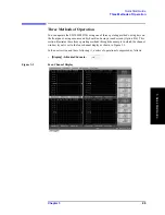
Page 49: ...he front panel using a mouse and keyboard and using a touch screen Option 016 This section illustrates these three operating methods through the example in which the channel window layout is set to the four channel display as shown in Figure 3 3 In the next section and those following it a series of operations is expressed as follows Display Allocate Channels Figure 3 3 Four Channel Display ...

Page 50: ... Keys Step 1 Press the key in the RESPONSE Block Figure 3 4 Step 1 Step 2 Press the or the key to move the cursor to the Allocate Channels button then press the or the key Figure 3 5 Step 2 Press the or the key to move the cursor to the button then press the key Figure 3 6 Step 3 ...

Page 51: ...ods of Operation 3 Quick Start Guide Operation Method Using a Mouse Step 1 From the Response menu click the Display button Figure 3 7 Step 1 Step 2 Click the Allocate Channels button Figure 3 8 Step 2 Step 3 Click the button Figure 3 9 Step 3 ...

Page 52: ...ation Operation Method Using the Touch Screen Option 016 Step 1 Press the Display button after presetting the E5070B E5071B Executing key Figure 3 10 Step 1 Step 2 Press the Allocate Channels button Figure 3 11 Step 2 Press the button Figure 3 12 Step 3 ...

Page 53: ...lecting the S parameter R Selecting the data format R Specifying the frequency range R Specifying the number of measurement points R Specifying the power level R Specifying the IF bandwidth STEP 2 Calibration R Specifying the calibration kit R Selecting the calibration type R Measuring the calibration data R Making the error correction ON R Saving the calibration data STEP 3 Connecting the device ...

Page 54: ...ransmission characteristics set the S parameter to S12 Step 3 Set the data format to the log magnitude format Format Log Mag Step 4 Set the center frequency to the bandpass filter center frequency Next specify the span frequency which is set to 200 MHz in this measurement example Center 9 4 7 5 M μ Span 2 0 0 M μ NOTE When entering the frequency unit using the keyboard type G for GHz M for MHz and...

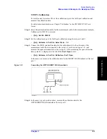
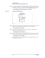
Page 55: ...calibration using the test port 1 and 2 Cal Calibrate 2 Port Cal Select Ports 1 2 Step 3 Connect the OPEN standard included in the calibration kit to the other end of the measurement cable that is connected to the test port 1 as shown in Figure 3 13 and measure the open calibration data at the test port 1 After measuring the open calibration data symbol is displayed to the left of the Port 1 Open ...

Page 56: ...ibration measurement DONE The calibration factor is calculated based on the calibration data acquired and the error correction is turned ON Cal Calibrate 2 Port Cal Done Step 7 Select the type in which the data is to be saved before saving the calibration factor calculated based on the calibration data Save Recall Save Type State Cal Step 8 Store the calibration file to the disk of the E5070B E507...

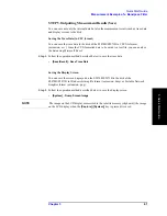
Page 57: ... the setting value for the power level 10 dBm may destroy some DUTs Should this occur first select the proper power level and then connect the DUT to the E5070B E5071B Step 2 Set the appropriate scale by executing the auto scale See Figure 3 16 Scale Auto Scale You can also adjust the scale by entering arbitrary values in the Scale Div button Reference Position button and Reference Value Figure 3 ...

Page 58: ...B bandwidth Measuring the Insertion Loss Step 1 Display a marker Marker Marker 1 Step 2 Using one of the following methods move the marker to the center frequency of the bandpass filter On the entry bar press 9 4 7 5 M μ Turn the rotary knob on the front panel to set it to the center frequency 947 5 MHz Step 3 Read the marker value displayed as shown in Figure 3 17 In this example the response val...

Page 59: ...enter frequency 947 5 MHz Step 3 Specify the bandwidth definition value that defines the pass band of the filter In this measurement example it is set to 3 dB Marker Search Bandwidth Value 3 x 1 Step 4 Set the bandwidth search function ON Marker Search Bandwidth Step 5 The bandwidth data items BW cent low high Q loss will be displayed See Figure 3 18 Table 3 1 Parameters for the Bandwidth Search F...

Page 60: ...60 Chapter3 Quick Start Guide Measurement Example of a Bandpass Filter Figure 3 18 Measuring the 3 dB Bandwidth ...

Page 61: ...d is a text file you can analyze the data using Microsoft Excel Step 1 Follow the operation method described below to save the trace data Save Recall Save Trace Data Saving the Display Screen You can save the screen displayed on the E5070B E5071B to the disk of the E5070B E5071B in Windows bitmap file format extension bmp or Portable Network Graphics format extension png Step 1 Follow the operatio...

Page 62: ...62 Chapter3 Quick Start Guide Measurement Example of a Bandpass Filter ...

Page 63: ... Changes A Manual Changes This appendix contains the information required to adapt this manual to versions or configurations of the E5070B E5071B manufactured earlier than the current printing date of this manual ...

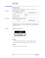
Page 64: ... the last five digits are the suffix Figure A 1 Example of Serial Number Plate Change 2 CD ROM of the Agilent IO Libraries Suite is added as standard accessories Sample program disk and VBA sample program disk are deleted as options Change 1 GPIB adapter is added as standard accessories Table A 1 Manual Changes by Serial Number Serial Prefix or Number Make Manual Changes MY424 Change 2 MY42100211 ...

Page 65: ...lay names and descriptions of the LCD screen 47 saving the display screen 61 turning the date time display ON and OFF 37 Documentation Warranty 5 DUT connecting the DUT 57 E E5070B E5071B basic measurement procedures 53 items packaged with the E5070B E5071B 18 overview of the E5070B E5071B 13 starting the E5070B E5071B 34 three methods of operation 49 Ecal module connecting the Ecal module 30 ENTR...

Page 66: ...cable options 31 power on test 41 shutdown 34 turning the power ON and OFF 34 verification and connection of power cable 31 power supply blown fuse 33 presetting the E5070B E5071B 54 printer connecting the printer 29 product overview of the E5070B E5071B 13 Professional Setup wizard 38 Programmer s Guide 7 Q Q bandwidth search function 59 Quick Start Guide 7 contents 12 R rack mount and handle kit...

Page 67: ...g the date time 36 title channel title bar 48 trace bar 48 trace data saving trace data 61 transmission measurement example of a bandpass filter 54 typeface conventions 6 U USB port front panel 47 User s Guide 7 V VBA Programmer s Guide 7 W Windows 2000 38 ...

Page 68: ... 1 800 452 4844 fax 1 888 900 8921 Canada Test and Measurement Call Center tel 1 877 894 4414 fax 1 888 900 8921 China tel 800 810 0189 fax 800 820 2816 Europe tel 31 20 547 2323 fax 31 20 547 2390 Japan Call Center tel 0120 421 345 tel 81 426 56 7832 fax 81 426 56 7840 Korea tel 82 2 2004 5004 fax 82 2 2004 5115 Latin America tel 305 269 7500 fax 305 269 7599 Taiwan tel 0800 047 866 fax 0800 286 ...

Reviews: