Chapter 4
165
Calibration
Adapter Characterization
4. Cal
ibra
tion
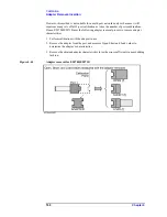
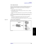
Execution procedure of characterization for test fixture using probe
The adapter characterization function also lets you obtain the characteristics of a test
fixture that is inserted between the instrument and a DUT that cannot be connected directly
to the instrument. In this case, a probe is used, and the obtained characteristics are saved to
a 2-port Touchstone file. The obtained result can be eliminated by using the network
de-embedding of the fixture simulator function, which permits measurement by
eliminating the effect of the test fixture.
NOTE
For more information on test fixture characterization using a probe, see Product Note
E5070/71-4.
1. Setting Stimulus Conditions
Set the stimulus condition of the channel for which you will execute the test fixture
characterization.
2. Performing Calibration
Perform 1-port calibration for the probe in the channel for which the stimulus condition has
been set.
3. Starting VBA Macro
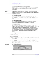
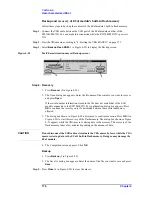
Start the VBA macro to display the Adapter Characterization screen (Figure 4-41).
4. Selecting Channel
Select the channel for which calibration has been performed (2 in Figure 4-41).
5. Setting Characterization
Step 1.
Press
Setup
(3 in Figure 4-41) to display the Setup dialog box (Figure 4-42).
Step 2.
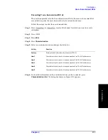
Make the setting of the calibration kit used in Cal Kit 1 (1 in Figure 4-42).
Step 3.
Enter the Delay of the test fixture (3 in Figure 4-42).
Step 4.
Enter a comment about the test fixture (4 in Figure 4-42). This comment is added to the
comment line at the beginning of the Touchstone file.
Step 5.
Check the box to the left of Swap ports while saving (5 in Figure 4-42) to align the
direction when specifying a file in the network de-embedding function.
Step 6.
Check the box to the left of One-sided measurement Only (6 in Figure 4-42).
Step 7.
Press
Close
(7 in Figure 4-42) to close the Setup dialog box.
Summary of Contents for E5070B
Page 6: ......
Page 30: ...24 Contents ...
Page 34: ...28 Chapter1 Precautions Before contacting us ...
Page 286: ...280 Chapter6 Data Analysis Using the Equation Editor ...
Page 430: ...424 Chapter12 Optimizing Measurements Performing a Segment by Segment Sweep segment sweep ...
Page 538: ...532 Chapter15 Measurement Examples Executing Power Calibration ...
Page 634: ...628 AppendixB Troubleshooting Warning Message ...
Page 732: ...726 AppendixD Softkey Functions Trigger Menu ...
Page 740: ...734 AppendixE General Principles of Operation Data Processing ...
Page 760: ...754 AppendixF Replacing the 8753ES with the E5070B E5071B Comparing Functions ...


