Chapter 2
33
Overview of Functions
Front Panel: Names and Functions of Parts
2.
Overvie
w
of Fun
ction
s
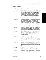
4. RESPONSE Block
A group of keys used mainly for setting up response measurements on the
E5070B/E5071B.
Key
Changes between normal and maximum display of the active
channel window. In normal display, all of the defined channel
windows (both active and non-active) are displayed in split
views on the screen. In maximum display, only the active
channel window is displayed over the entire area, with
non-active windows not displayed. To maximize the active
channel, double-click the channel window frame.
Measurements are also carried out on the non-active channels
that are not displayed.
Key
Changes between normal and maximum display of the active
trace. In normal display, all of the traces defined on the
channel (both active and non-active) are displayed on the
screen. In maximum display, only the active trace is displayed
over the entire area, with non-active traces not displayed. To
maximize the active trace, double-click the area inside the
channel window (excluding the frame). Measurements are
also carried out on the non-active traces not displayed.
Key
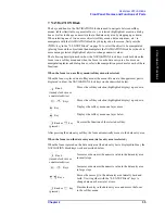
Displays the “Measurement Menu” on page 701 on the right
side of the screen. Manipulating the “Measurement Menu”
enables you to specify the measurement parameters (types of
S-parameters) for each trace.
Key
Displays the “Format Menu” on page 692 on the right side of
the screen. Manipulating the “Format Menu” enables you to
specify the data format (data transformation and graph
formats) for each trace.
Key
Displays the “Scale Menu” on page 713 on the right side of
the screen. Manipulating the “Scale Menu” enables you to
specify the scale for displaying a trace (magnitude per
division, value of the reference line, etc.) for each trace. You
can also specify the electrical delay and phase offset for each
trace.
Key
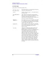
Displays the “Display Menu” on page 688 on the right side of
the screen. Manipulating the “Display Menu” enables you to
specify the number of channels and the channel window array,
the number and arrangement of traces, the setup for data math,
etc.
Key
Displays the “Average Menu” on page 662 on the right side of
the screen. Manipulating the “Average Menu” enables you to
define the averaging, smoothing, and IF bandwidth.
Key
Displays the “Calibration Menu” on page 663 on the right side
of the screen. Manipulating the “Calibration Menu” enables
you to turn the calibration and error correction on/off and
change definitions for calibration kits.
Summary of Contents for E5070B
Page 6: ......
Page 30: ...24 Contents ...
Page 34: ...28 Chapter1 Precautions Before contacting us ...
Page 286: ...280 Chapter6 Data Analysis Using the Equation Editor ...
Page 430: ...424 Chapter12 Optimizing Measurements Performing a Segment by Segment Sweep segment sweep ...
Page 538: ...532 Chapter15 Measurement Examples Executing Power Calibration ...
Page 634: ...628 AppendixB Troubleshooting Warning Message ...
Page 732: ...726 AppendixD Softkey Functions Trigger Menu ...
Page 740: ...734 AppendixE General Principles of Operation Data Processing ...
Page 760: ...754 AppendixF Replacing the 8753ES with the E5070B E5071B Comparing Functions ...

