Chapter 4
233
Calibration
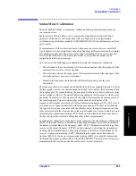
Scalar-Mixer Calibration
4. Cal
ibra
tion
Scalar-Mixer Calibration
The E5070B/E5071B has a scalar-mixer calibration function for measuring frequency
conversion devices.
Scalar-mixer calibration allows you to measure the magnitude value and reflection
parameter of the mixer’s conversion loss with very high accuracy by performing
calibration using calibration standards (OPEN/SHORT/LOAD) in combination as well as a
power meter.
For measurement of the conversion loss in a frequency conversion device, normal full
2-port calibration is not available because of the frequency difference between the stimulus
port and the response port. Therefore, scalar-mixer calibration allows you to correct the
error term that resides in a full 2-port error model by using the error model and an
expression based on a new concept.
You can correct the following error elements by using the scalar-mixer calibration.
•
The reflection between the output port of the network analyzer and the input port of the
measured mixer (vector error correction).
•
The reflection between the output port of the measured mixer and the input port of the
network analyzer (vector error correction).
•
Transmission frequency characteristics at different frequencies (scalar error
correction).
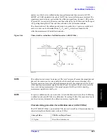
The frequency-offset error model can be described by the flow graph in Figure 4-74. From
the flow graph it can be seen that the model is divided in two halves: the stimulus port and
the response port. By conceptualizing the error model in these two halves, each error term
can be isolated to either of the model’s halves depending on the frequency at which it was
generated. The majority of the signals will only affect measurements by causing errors at
the same frequency. Two error signals that are functions of both halves of the
frequency-offset model are isolation (EXF) and transmission tracking (ETF). EXF is set to
zero because it is cannot be detected by the frequency change. ETF must be divided into
two types of errors: one associated with the stimulus side at the input frequencies and the
other associated with the response side at the output frequencies. As previously discussed,
calculating the transmission tracking (ETF) based on both stimulus and response sides is
the key to using error correction during frequency-offset measurements.
In scalar-mixer calibration, use the power meter to measure the transmission tracking error
(ESTF) of the signal source in both the output and input frequencies in order to calculate
the transmission tracking in the frequency-offset (ETF). The transmission tracking of the
receiver in the output frequency (ERTF) can be determined by dividing the transmission
tracking (ETF) calculated based on the output frequency in full 2-port calibration by the
receiver’s transmission tracking (ESTF). Multiplying the signal source transmission
tracking (ESTF) by the receiver transmission tracking (ERTF) provides the transmission
tracking in the frequency-offset (ETF). Since ESTF and ERTF are products of two power
measurements, the resulting correction coefficient is a scalar parameter.
Summary of Contents for E5070B
Page 6: ......
Page 30: ...24 Contents ...
Page 34: ...28 Chapter1 Precautions Before contacting us ...
Page 286: ...280 Chapter6 Data Analysis Using the Equation Editor ...
Page 430: ...424 Chapter12 Optimizing Measurements Performing a Segment by Segment Sweep segment sweep ...
Page 538: ...532 Chapter15 Measurement Examples Executing Power Calibration ...
Page 634: ...628 AppendixB Troubleshooting Warning Message ...
Page 732: ...726 AppendixD Softkey Functions Trigger Menu ...
Page 740: ...734 AppendixE General Principles of Operation Data Processing ...
Page 760: ...754 AppendixF Replacing the 8753ES with the E5070B E5071B Comparing Functions ...

