Chapter 7
309
Fixture Simulator
Example of Using Fixture Simulator
7
. F
ixt
ur
e
Sim
ula
to
r
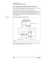
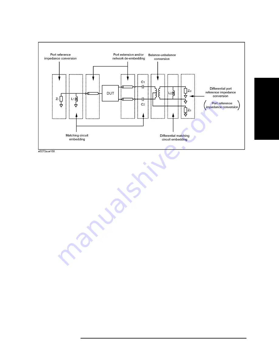
Figure 7-23
Measurement circuit simulated by fixture simulator
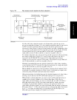
First, the effect of an undesired network can be eliminated by port extension and/or
network de-embedding. In Figure 7-22, since calibration standards cannot be connected to
the DUT terminals to perform calibration, calibration should be performed at the
connectors to the test fixture. Using port extension and/or network de-embedding enables
you to remove an undesired network by using data processing and moving the calibration
reference plane to the DUT’s side equivalently. This function is performed for a
single-ended port even if balance-unbalance conversion is applied to the port.
Port reference impedance conversion converts measured S-parameters to those at arbitrary
port reference impedance. In Figure 7-22, since the single-ended port of the DUT is
connected to the E5070B/E5071B’s test port (50
Ω
, single-ended), port reference
impedance conversion is not required. This function is performed for a single-ended port
even if balance-unbalance conversion is applied to the port.
Matching circuit embedding converts measured S-parameters to those when a matching
circuit is added to the DUT’s terminal. This function is performed for a single-ended port
even if balance-unbalance conversion is applied to the port.
Balance-unbalance conversion converts S-parameters measured at an unbalanced state to
mixed-mode S-parameters measured at a balanced state. The balanced port signal can be
evaluated by using differential mode and common mode signals.
Differential matching circuit embedding converts measured S-parameters to those when a
matching circuit is added to the DUT’s differential mode port.(L2 in Figure 7-23)
Differential port reference impedance conversion converts a differential port reference
impedance to an arbitrary impedance. Port reference impedance Z [
Ω
] at the two
single-ended ports before balance conversion is automatically converted to 2Z [
Ω
] for
differential mode port and Z/2 [
Ω
] for common mode port after balance conversion.
Accordingly, if port reference impedance conversion is not performed for the two
single-ended ports before balance conversion, differential mode port reference impedance
Zd becomes 50
Ω
×
2 = 100
Ω
, and common mode port reference impedance Zc becomes
50
Ω
/ 2 = 25
Ω
. Since the differential port is terminated with 200
Ω
in Figure 7-20,
differential port reference impedance Zd should be set to 200
Ω
.
Summary of Contents for E5070B
Page 6: ......
Page 30: ...24 Contents ...
Page 34: ...28 Chapter1 Precautions Before contacting us ...
Page 286: ...280 Chapter6 Data Analysis Using the Equation Editor ...
Page 430: ...424 Chapter12 Optimizing Measurements Performing a Segment by Segment Sweep segment sweep ...
Page 538: ...532 Chapter15 Measurement Examples Executing Power Calibration ...
Page 634: ...628 AppendixB Troubleshooting Warning Message ...
Page 732: ...726 AppendixD Softkey Functions Trigger Menu ...
Page 740: ...734 AppendixE General Principles of Operation Data Processing ...
Page 760: ...754 AppendixF Replacing the 8753ES with the E5070B E5071B Comparing Functions ...

