Chapter 15
517
Measurement Examples
Measuring an Unbalanced and Balanced Bandpass Filter
15
. Me
asur
eme
n
t Exa
m
ple
s
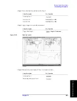
8. Adding a Matching Circuit
Here, add an inductance of 47 nH in parallel to port 2 on the DUT (balanced). It is also
possible to add a matching circuit to the port before unbalanced-balanced conversion. For
more information, see “Determining the Characteristics that Result from Adding a
Matching Circuit to a Differential Port” on page 303.
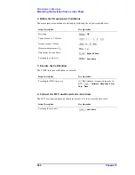
Setting Description
Key Operation
Selecting a matching circuit:
Shunt L - Shunt C
Return
(or
-
Fixture Simulator
) -
Diff. Matching
-
Select Circuit
-
Shunt
L-Shunt C
Inductance: 47 nH
L
-
C=0, G=0, R=0
(checks that
C
,
G
, and
R
have been set to
0
.)
Differential matching circuit function: ON
Diff. Matching
(turns it
ON
)
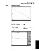
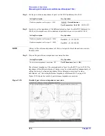
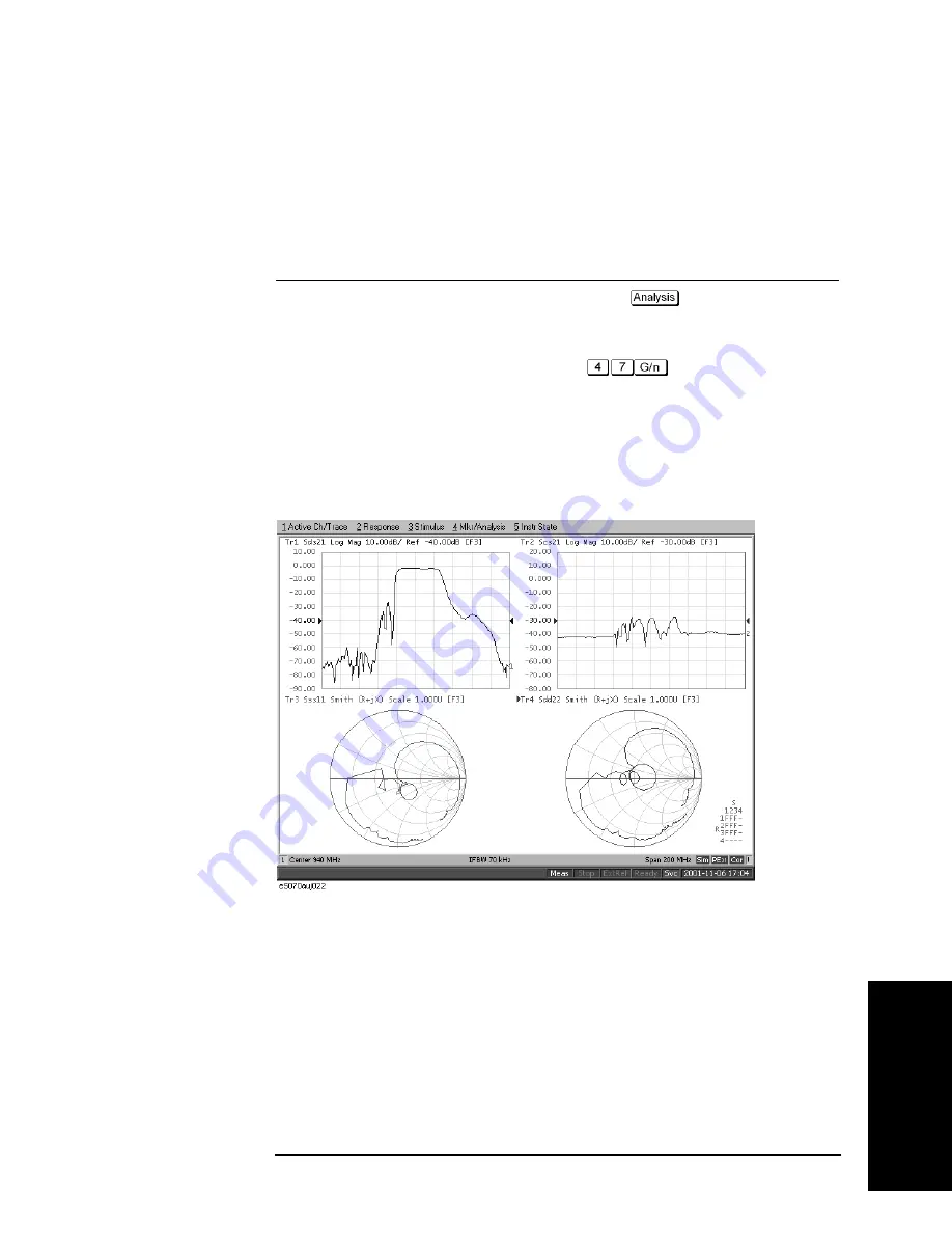
Figure 15-31 shows the results of adding a matching circuit.
Figure 15-31
Results of adding a matching circuit (47 nH)
Summary of Contents for E5070B
Page 6: ......
Page 30: ...24 Contents ...
Page 34: ...28 Chapter1 Precautions Before contacting us ...
Page 286: ...280 Chapter6 Data Analysis Using the Equation Editor ...
Page 430: ...424 Chapter12 Optimizing Measurements Performing a Segment by Segment Sweep segment sweep ...
Page 538: ...532 Chapter15 Measurement Examples Executing Power Calibration ...
Page 634: ...628 AppendixB Troubleshooting Warning Message ...
Page 732: ...726 AppendixD Softkey Functions Trigger Menu ...
Page 740: ...734 AppendixE General Principles of Operation Data Processing ...
Page 760: ...754 AppendixF Replacing the 8753ES with the E5070B E5071B Comparing Functions ...

