62
Chapter 3
Setting Measurement Conditions
Setting Channels and Traces
Step 5.
Press
Return
. The dialog box that prompts you to restart the firmware appears. Click the
Yes
button to restart the firmware.
Setting channel display (layout of channel windows)
The measurement result for each channel is displayed in its dedicated window (channel
window). You cannot have a single window display the measurement results from more
than one channel. This means that the setting of the window layout determines the number
of channels displayed on screen.
NOTE
The execution of measurement for each channel does not depend on how the channel is
displayed (channels that are not displayed can be measured). For information on executing
measurement for each channel (trigger mode and trigger source), refer to Chapter 5,
“Making Measurements,” on page 241.
The procedure for setting the window layout is as follows:
Step 1.
Press
.
Step 2.
Press
Allocate Channels
.
Step 3.
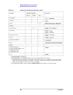
Press the desired softkey to select the window layout (refer to Figure 3-1).
Summary of Contents for E5070B
Page 6: ......
Page 30: ...24 Contents ...
Page 34: ...28 Chapter1 Precautions Before contacting us ...
Page 286: ...280 Chapter6 Data Analysis Using the Equation Editor ...
Page 430: ...424 Chapter12 Optimizing Measurements Performing a Segment by Segment Sweep segment sweep ...
Page 538: ...532 Chapter15 Measurement Examples Executing Power Calibration ...
Page 634: ...628 AppendixB Troubleshooting Warning Message ...
Page 732: ...726 AppendixD Softkey Functions Trigger Menu ...
Page 740: ...734 AppendixE General Principles of Operation Data Processing ...
Page 760: ...754 AppendixF Replacing the 8753ES with the E5070B E5071B Comparing Functions ...


