Chapter 4
203
Troubleshooting
Performance test failure troubleshooting
4. T
ro
uble
shoo
tin
g
###: Most suspicious assembly
##: Suspicious assembly
#: Possible faulty assembly
Performance test failure troubleshooting
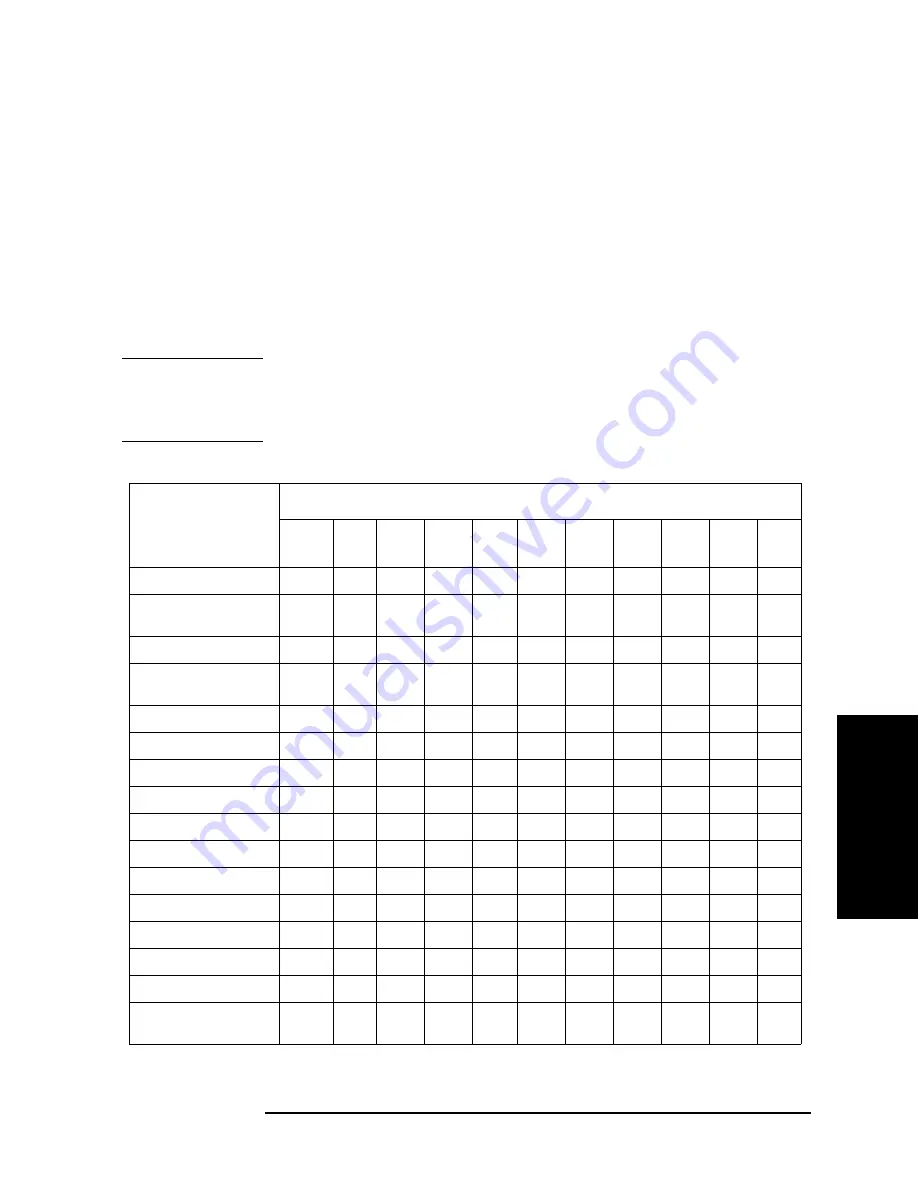
Table 4-7 represents the relationships between the failed test and probable faulty assembly.
If the performance test failure cannot be removed by a proper adjustment, replace the
assembly shown in this table.
Note that this table lists some typical cases. There are possibilities that other assembly may
be faulty. To troubleshoot further, perform the diagnostics test procedures.
NOTE
When Crosstalk, System dynamic range or Uncorrected system performance test fails,
check first whether the connections of the RF semi-rigid cables between the suspicious
assembly and others are tight or loose. Also check for possible disconnection (impairment)
of the cables and connectors.
Table 4-7
Performance test failure troubleshooting information
First failed test
Probable faulty board assembly or parts
OCXO
BAS
SYN
-SRC
SYN
-LCL
VNR
RCV
-1
RCV
-2
RCV
-3
RCV
-4
T2
-SW
CBL
AUX Input
###
Frequency Accuracy
(Standard)
#
###
##
#
Frequency Accuracy (1E5)
#
#
###
##
#
RF Output Level Accuracy
& Flatness
##
###
#
RF Output Level Linearity
##
###
#
Trace Noise (S11)
##
##
#
###
#
Trace Noise (S22)
##
##
#
###
#
Trace Noise (S33)
##
##
#
###
#
Trace Noise (S44)
##
##
#
###
#
Trace Noise (S21, S12)
##
##
#
###
###
#
Trace Noise (S43, S34)
##
##
#
###
###
#
Crosstalk (S21, S12)
#
#
#
##
##
###
###
Crosstalk (S32)
#
#
#
##
##
###
###
Crosstalk (S43)
#
#
#
##
##
###
###
Crosstalk (S14)
#
#
#
##
##
###
###
System Dynamic Range
(S21)
##
##
#
###
#
Summary of Contents for E5071C
Page 14: ...14 Contents ...
Page 168: ...168 Chapter2 Performance Test E5071C Performance Test Record ...
Page 212: ...212 Chapter4 Troubleshooting To configure the CPU Mother Board Assembly and BIOS ...
Page 262: ...262 Chapter5 Replaceable Parts Power Cables and Plug Configurations ...
Page 326: ...326 Chapter6 Replacement Procedure Probe Power and Power Switch Board Replacement ...
Page 332: ...332 Chapter7 Post Repair Procedures Post Repair Procedures ...
Page 360: ...360 AppendixB System Recovery Calibration of the Touch Screen ...
Page 364: ...364 AppendixC Firmware Update Firmware Update ...
Page 365: ...365 D Power Requirement D Power Requirement ...


