Chapter 6
283
Replacement Procedure
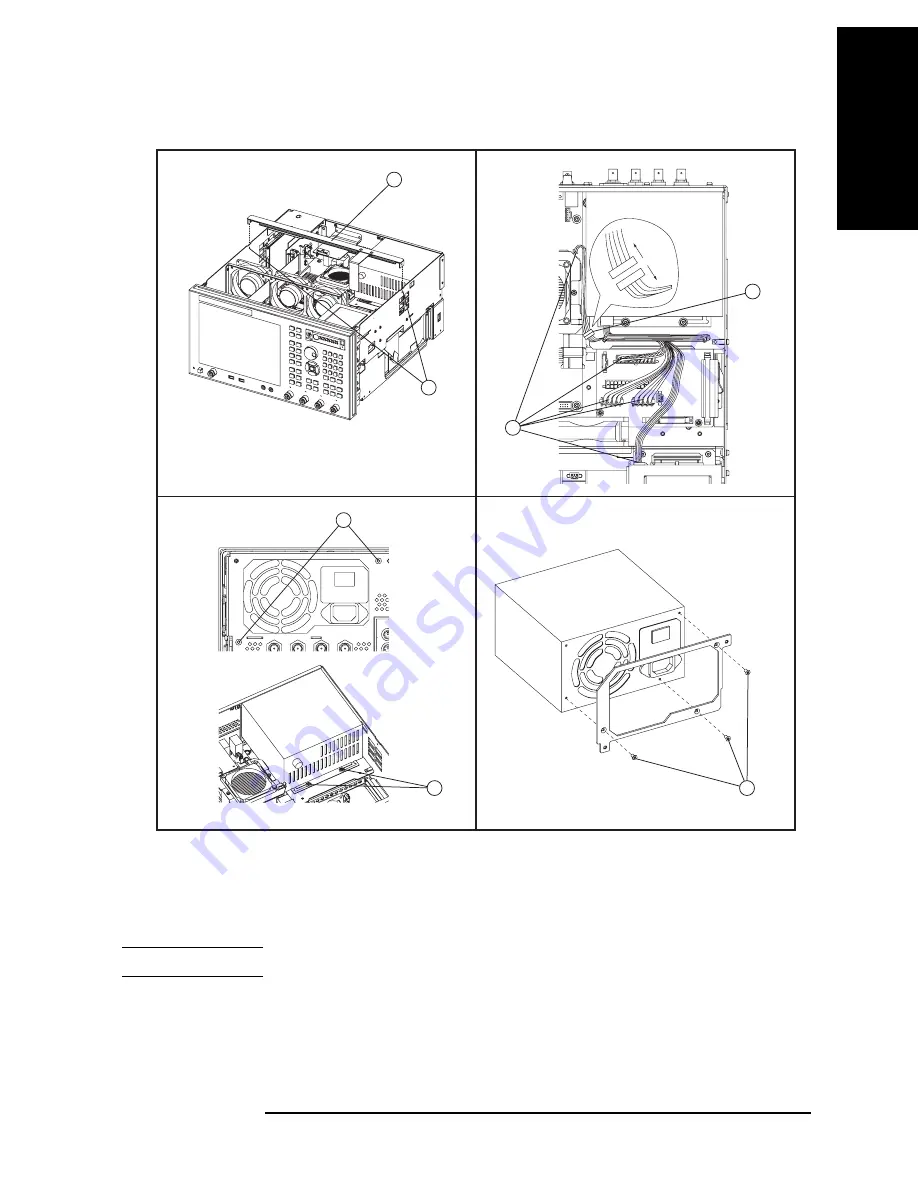
Power Supply Assembly Replacement
6. Re
placem
ent Pro
ce
d
ur
e
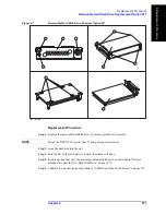
Figure 6-11
Power Supply Assembly Removal
e5071cse1098
2
4
3
1
5
6
7
Replacement Procedure
Step 1.
Replace the power supply assembly by inverse procedure of removal.
NOTE
Fasten the TORX T10 screws (item 7) using a torque screwdriver.
Summary of Contents for E5071C
Page 14: ...14 Contents ...
Page 168: ...168 Chapter2 Performance Test E5071C Performance Test Record ...
Page 212: ...212 Chapter4 Troubleshooting To configure the CPU Mother Board Assembly and BIOS ...
Page 262: ...262 Chapter5 Replaceable Parts Power Cables and Plug Configurations ...
Page 326: ...326 Chapter6 Replacement Procedure Probe Power and Power Switch Board Replacement ...
Page 332: ...332 Chapter7 Post Repair Procedures Post Repair Procedures ...
Page 360: ...360 AppendixB System Recovery Calibration of the Touch Screen ...
Page 364: ...364 AppendixC Firmware Update Firmware Update ...
Page 365: ...365 D Power Requirement D Power Requirement ...


