234
Chapter 5
Replaceable Parts
Replaceable Parts List
Rear View (2)
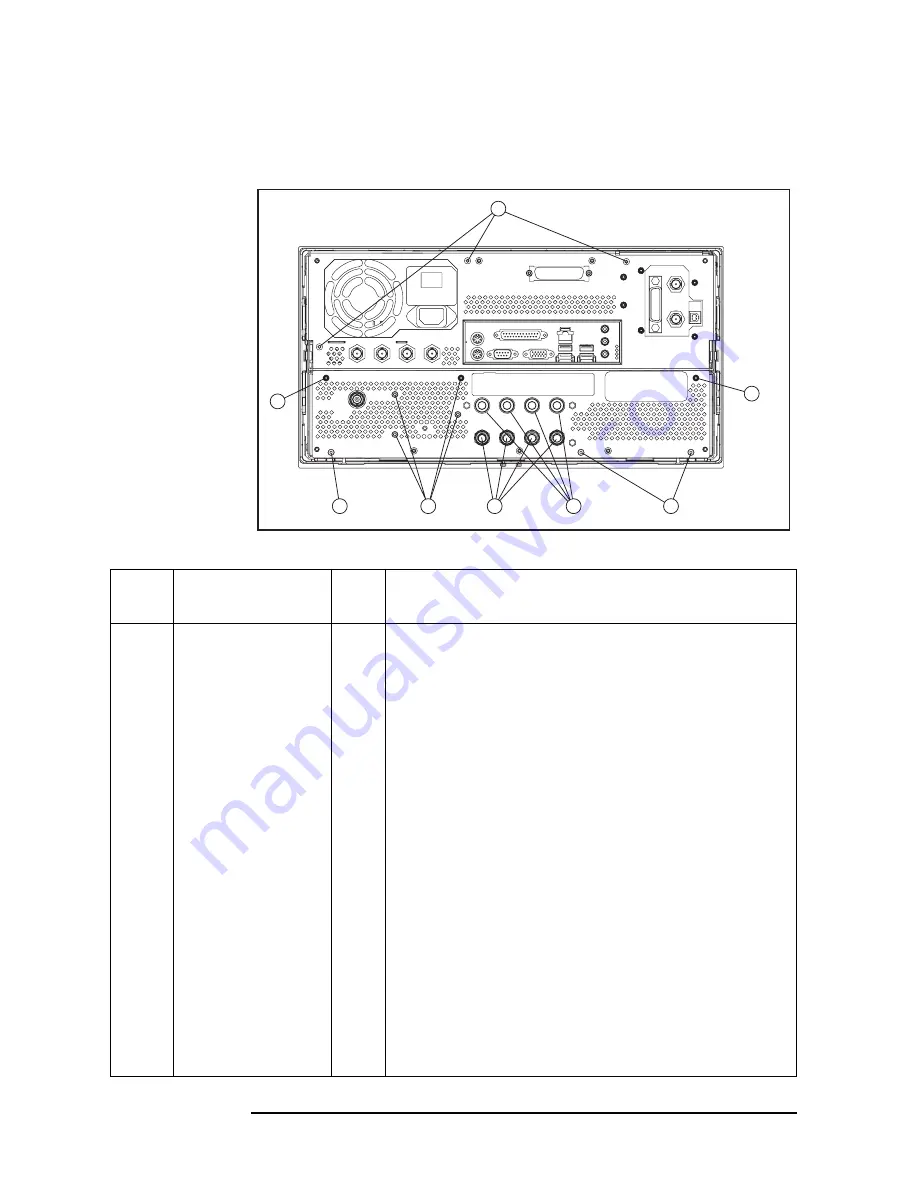
Figure 5-12
Rear View (2)
e5071cse1092
1
2
3
4
5
2
3
2
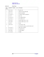
Table 5-12
Rear View (2)
Ref.
Desig.
Agilent Part Number
Qty.
Description
1
0515-1946
3
SCREW-MACH M3.0 x L6 FL T10
2
0515-0430
6
SCREW-MACH M3.0 x L6 PN T10
3
0515-1946
3
SCREW-MACH M3.0 x L6 FL T10
4
2950-0035
2
NUT (Opt. 235, 285)
2190-0102
2
WASHER (Opt. 235, 285)
6960-0524
2
PLUG-HOLE (Opt. 235, 285)
2950-0035
4
NUT (Opt. 435, 485)
2190-0102
4
WASHER (Opt. 435, 485)
6960-0524
4
PLUG-HOLE (Opt. 230, 280, 430, 480)
5
2110-0046
2
FUSE 5A 125V (Opt. 235, 285)
1400-0112
2
FUSE HOLDER CAP (Opt. 235, 285)
6960-0309
2
PLUG-HOLE (Opt. 235, 285)
2110-0046
4
FUSE 5A 125V ( Opt. 435, 485)
1400-0112
4
FUSE HOLDER CAP ( Opt. 435, 485)
6960-0309
4
PLUG-HOLE ( Opt. 430, 480)
Summary of Contents for E5071C
Page 14: ...14 Contents ...
Page 168: ...168 Chapter2 Performance Test E5071C Performance Test Record ...
Page 212: ...212 Chapter4 Troubleshooting To configure the CPU Mother Board Assembly and BIOS ...
Page 262: ...262 Chapter5 Replaceable Parts Power Cables and Plug Configurations ...
Page 326: ...326 Chapter6 Replacement Procedure Probe Power and Power Switch Board Replacement ...
Page 332: ...332 Chapter7 Post Repair Procedures Post Repair Procedures ...
Page 360: ...360 AppendixB System Recovery Calibration of the Touch Screen ...
Page 364: ...364 AppendixC Firmware Update Firmware Update ...
Page 365: ...365 D Power Requirement D Power Requirement ...

