286
Chapter 6
Replacement Procedure
Handler I/O Board Replacement
Handler I/O Board Replacement
Tools Required
•
TORX screwdriver, T10, T15, and T20
Removal Procedure
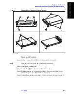
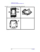
Refer to Figure 6-13 for this procedure.
Step 1.
Remove the outer cover as described in “Outer Cover Removal” on page 266.
Step 2.
Disconnect the flat cable (item 1) from the handler I/O board.
Step 3.
Remove the two TORX T10 screws (item 2) fastening the handler I/O board.
Step 4.
Slide the handler I/O board toward backward (item 3).
Summary of Contents for E5071C
Page 14: ...14 Contents ...
Page 168: ...168 Chapter2 Performance Test E5071C Performance Test Record ...
Page 212: ...212 Chapter4 Troubleshooting To configure the CPU Mother Board Assembly and BIOS ...
Page 262: ...262 Chapter5 Replaceable Parts Power Cables and Plug Configurations ...
Page 326: ...326 Chapter6 Replacement Procedure Probe Power and Power Switch Board Replacement ...
Page 332: ...332 Chapter7 Post Repair Procedures Post Repair Procedures ...
Page 360: ...360 AppendixB System Recovery Calibration of the Touch Screen ...
Page 364: ...364 AppendixC Firmware Update Firmware Update ...
Page 365: ...365 D Power Requirement D Power Requirement ...

