Chapter 3
143
Troubleshooting
E5092A Setting Troubleshooting
3. T
ro
uble
s
hoo
tin
g
suspect.
•
If the voltage of ADC2 is not within the limit, the A1 board or the heater is suspect.
Check the voltage output of the Control Lines
Step 1.
Turn on the E5092A.
Step 2.
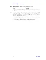
Measure the DC voltage between the pin 12 and 15 on the control lines using a voltmeter
with a small probe. Figure 3-5 shows the pin assignment of the control lines.
Figure 3-5
Pin assignment of the control lines
Step 3.
Rotate the voltage adjustment trimmer on the front panel. Check that the trimmer can set
the voltage from +2V to +5V.
•
If the output voltage can not be varied from +2V to +5V though the A1 board works
correctly, the A3 DUT control board is suspect.
•
If the output voltage is good, the A3 board is verified.
Check control lines setting
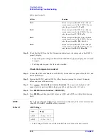
The E5092A can control the output from the control line (Figure 3-5) of the E5092A and
control the DUT (for example, switching the frequency band of the front end module).
Step 1.
Short between the pin 12 - 13 and the pin 14 - 15.
Step 2.
Press
-
Multiport Test Set Setup
to display the Multiport Test Set Setup menu.
Step 3.
Press
Test Set 1
and then select the ID of the E5092A The ID is set with the bit switch on
the real panel of the E5092A.
Step 4.
Press
Control Lines
from group A until group D to the setting menu of the DUT control
line.
Summary of Contents for E5092A
Page 10: ...4 ...
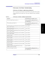
Page 140: ...134 Chapter2 Performance Tests E5092A Performance Test Record ...
Page 152: ...146 Chapter3 Troubleshooting Performance Test Failure Troubleshooting ...
Page 180: ...174 Chapter4 Replaceable Parts Replaceable Parts List for E5092A 020 ...
Page 205: ...199 B Power Requirement A Power Requirement ...


