182
Chapter 5
Replacement Procedure
Replacement Procedure for E5092A-020
Power Supply Assembly Removal
Tools Required
•
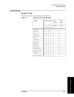
TORX screwdriver, T10, T15 and T20.
Procedure
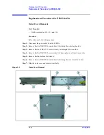
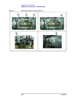
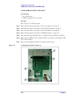
Refer to Figure 5-5 for this procedure.
Step 1.
Remove the outer cover as described in “Outer Cover Removal” on page 178.
Step 2.
Remove the A1 switch control board as described in “A1 Switch Control Board Removal”
on page 181.
Step 3.
Disconnect the two power cable (item 1).
Step 4.
Remove the four TORX T10 screw (item 2) from the bottom.
Step 5.
Remove the power supply board from the chassis.
Figure 5-5
Power Supply Assembly Removal
Summary of Contents for E5092A
Page 10: ...4 ...
Page 140: ...134 Chapter2 Performance Tests E5092A Performance Test Record ...
Page 152: ...146 Chapter3 Troubleshooting Performance Test Failure Troubleshooting ...
Page 180: ...174 Chapter4 Replaceable Parts Replaceable Parts List for E5092A 020 ...
Page 205: ...199 B Power Requirement A Power Requirement ...

