background image

Agilent E5270 TIS User’s Guide, Edition 1

1-13

Starting TIS Programming

Migration to Agilent 4070

Migration to Agilent 4070

The Agilent E5270 TIS library is a set of functions that provide the same synopsis as 
the Agilent 4070 TIS functions. So, if you create programs using the Agilent E5270 
TIS library, the programs can be used to control the Agilent 4070 tester with small 
change.

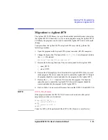
To migrate from the Agilent E5270 to Agilent 4070 successfully, perform the 
following procedure.

1. Open the program on the Agilent 4070 system controller (HP-UX computer).

2. Change the header file. The header file 

E5270_TIS.h

 is not required. Include 

the 

tis.h

 file instead.

#include "/opt/hp4070/include/tis.h"

3. Remove the following functions. They are not required for the Agilent 4070.

open_E5270

close_E5270

4. Remove the VXI

plug

&

play

 driver functions for Agilent E5270 if they are used 

in the program. The driver cannot be used to control the Agilent 4070. This part 
of program should be created and added to the program for the Agilent 4070.

5. Remove the 

vi_E5270

 function if it is used in the program. The function 

cannot be used to control the Agilent 4070. This part of program should be 
created and added to the program for the Agilent 4070.

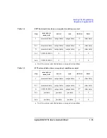
6. Refer to Table 1-3 and correct differences between the E5270 TIS and 4070 TIS.

NOTE

E5270_TIS_H macro

If the program includes the E5270_TIS_H macro as shown below, this part of 
program does not have to be deleted.

#ifdef E5270_TIS_H

/* codes for E5270 */

#else

/* codes for 4070 */

#endif

Codes for 4070 will be performed if the E5270_TIS_H macro is not effective.

Summary of Contents for E5270 Series

Page 1: ...Agilent E5270 TIS User s Guide Agilent E5270 Series of Parametric Measurement Solutions E5270 90030 December 2002 Edition 1 ...

Page 2: ...turn the product to Buyer However Buyer shall pay all shipping charges duties and taxes for products returned to Agilent Technologies from another country Agilent Technologies do not warrant that the operation of Agilent Technologies products will be uninterrupted or error free If Agilent is unable within a reasonable time to repair or replace any product to a condition as warranted customer will ...

Page 3: ...s or its suppliers be liable for loss of date or for direct special incidental consequential including lost profit or date or other damage whether based in contract tort or otherwise For consumer transactions in Australia and New Zealand the warranty terms contained in this statement except to the extent lawfully permitted do not exclude restrict or modify and are in addition to the mandatory stat...

Page 4: ...uage users Measurement programs that include TIS functions are easier to maintain than programs written solely in the C language This manual describes the installation and reference information of the Agilent E5270 TIS and consists of the following chapters Starting TIS Programming Describes the intallation information of the Agilent E5270 TIS library and general information for programming TIS Fu...

Page 5: ...mming 1 8 Debugging 1 11 Migration to Agilent 4070 1 13 2 TIS Function Reference How to Use the Reference Pages 2 3 Function Name 2 3 Synopsis 2 3 Arguments 2 4 Example 2 4 See Also 2 4 Function Reference 2 5 Summary 2 5 Arguments 2 9 close_E5270 2 13 connect_pin 2 14 disable_port 2 15 disconnect_all 2 16 error_info 2 17 force_i 2 18 force_v 2 20 init_system 2 21 measure_bdv 2 22 measure_i measure...

Page 6: ...measure_p 2 30 measure_v measure_vt 2 32 port_status port_status_t 2 34 open_E5270 2 36 reset_timestamp 2 37 set_adc 2 38 set_bdv 2 40 set_ileak 2 42 set_iv 2 45 set_pbias 2 52 set_piv 2 57 set_smu_ch 2 63 set_sync 2 64 set_timestamp 2 67 status_miv 2 68 sweep_iv 2 69 sweep_miv 2 71 vi_E5270 2 74 ...

Page 7: ...Agilent E5270 TIS User s Guide Edition 1 1 Starting TIS Programming ...

Page 8: ...ser s Guide Edition 1 Starting TIS Programming This chapter describes the installation information of the Agilent E5270 TIS library and basic information for programming Installation TIS Programming Migration to Agilent 4070 ...

Page 9: ...vironment Microsoft Visual C or Borland C Builder It must be supported by the VISA I O library GPIB IEEE 488 interface and 32 bit VISA I O library Agilent GPIB interface with Agilent IO Libraries or equivalent Agilent E5270 VXIplug play driver The driver is required to use the Agilent E5270 TIS library The Agilent E5270 TIS library and VXIplug play driver are stored in the Software CD ROM furnishe...

Page 10: ... and check the GPIB interface See manual of the VISA I O library 4 Install the programming software Follow the setup program instructions 5 Install the Agilent E5270 VXIplug play driver a Insert the Agilent E5270 Series Software CD ROM to the CD ROM drive connected to your computer b Execute Pnp E5270 exe on the CD ROM The setup program installs the driver See Table 1 1 for the installed files The...

Page 11: ...dows XP Windows 2000 or Windows NT or Win95 for Windows 95 Description visa path Winxx Age5270 age5270 bas Driver for Microsoft Visual Basic visa path Winxx Age5270 age5270 c Driver source code visa path Winxx Age5270 age5270 def DLL export definition file visa path Winxx Age5270 age5270 fp Front panel file visa path Winxx Age5270 age5270 h Driver header file visa path Winxx Age5270 age5270 hlp On...

Page 12: ...tion user path lib msc E5270_TIS lib TIS library for Microsoft Visual C user path lib bc E5270_TIS lib TIS library for Borland C Builder user path E5270_TIS h TIS library header file user path E5270_TIS c TIS library source code user path Tis_gd pdf TIS User s Guide Electronic manual user path sample sample c Sample program source code This is just example program user path sample makefile Sample ...

Page 13: ...rmation for programming Planning Measurement Programming Debugging Planning Measurement Before starting programming decide the following items Measurement devices Discrete packaged on wafer and so on Characteristics to be measured hFE Vth sheet resistance and so on Measurement method Spot measurement staircase sweep measurement and so on ...

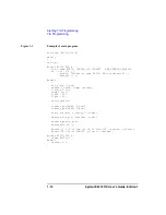
Page 14: ...nt E5270 folder Example include Agilent E5270 E5270_TIS h 2 Define the open_E5270 function to establish the connection with the Agilent E5270 The following example connects the Agilent E5270 of GPIB address 17 Example main int ret ifdef E5270_TIS_H ret open_E5270 GPIB0 17 INSTR ERR_DETECT_ON NULL if ret 0 printf E527x device open failed Exit program n return 1 endif 3 Create measurement routine Th...

Page 15: ..._TIS h is included The macro can be used to judge whether the E5270 TIS library is available or not and switch a program operation as the following example ifdef E5270_TIS_H codes for E5270 else codes for 4070 endif This example is used to switch codes to be performed If the E5270_TIS_H is effective the codes for E5270 will be performed Else the codes for 4070 will be performed An example shown in...

Page 16: ...ret 0 printf Failed to open E5270 Exit program n return 1 endif int h_pin l_pin double v_force comp current v_force 0 5 comp 1e 3 h_pin 12 l_pin 16 init_system connect_pin SMU3 h_pin connect_pin GNDU l_pin force_v h_pin v_force 0 comp measure_i h_pin current comp disable_port h_pin disconnect_all printf I 8 5f amp at 8 5f volt n current v_force printf R 8 3f ohm n v_force current ifdef E5270_TIS_H...

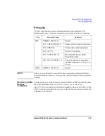
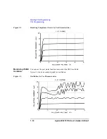
Page 17: ..._status function to monitor whether an SMU reached saturation that is the compliance value set by force_i force_v set_iv and so on Figure 1 2 shows an example in which the compliance value was set to 8 mA for the SMU As shown in the graph the top curve is flat and does not increase because the compliance is set to 8 mA Unit Returned Value Condition SMU NORMAL_MEAS 0 Normal DCS_COMP_OTHER 1 Another...

Page 18: ...g TIS Programming Figure 1 2 Reaching Compliance 8 mA Ic Vce Characteristics Monitoring if SMU Oscillates You can use the port_status function to monitor if an SMU oscillated Figure 1 3 shows an example graph for oscillation Figure 1 3 Oscillation Ic Vce Characteristics ...

Page 19: ... 3 Remove the following functions They are not required for the Agilent 4070 open_E5270 close_E5270 4 Remove the VXIplug play driver functions for Agilent E5270 if they are used in the program The driver cannot be used to control the Agilent 4070 This part of program should be created and added to the program for the Agilent 4070 5 Remove the vi_E5270 function if it is used in the program The func...

Page 20: ...s of setting period and width values period and width values automatically set when you specify period 0 set_piv Logarithmic sweep is available for 4070 set_sync The offset value is effective for logarithmic sweep using 4070 set_timestamp For 4070 this function must be executed before the port_status or status_miv function sweep_iv and sweep_miv Returned data when a sweep abort condition occurred ...

Page 21: ...ata output data output data 0 time data N measured data output data output data Xa a X will be a status code that indicates a sweep abort condition time data N 1 9999999 99999 0 0 5 0 Last 9999999 99999 0 0 5 0 step measure or meas_vals source sync statuses times 1 measured data output data output data 0 time data N 1 measured data output data output data 0 time data N 9999999 99999 output data ou...

Page 22: ...1 16 Agilent E5270 TIS User s Guide Edition 1 Starting TIS Programming Migration to Agilent 4070 ...

Page 23: ...Agilent E5270 TIS User s Guide Edition 1 2 TIS Function Reference ...

Page 24: ...2 2 Agilent E5270 TIS User s Guide Edition 1 TIS Function Reference This chapter is the complete reference of the Agilent E5270 TIS functions How to Use the Reference Pages Function Reference ...

Page 25: ...ll not contain the section that does not apply to the function Function Name The function name is shown at the top of the description module with a brief description Synopsis The synopsis of the function is printed in computer font as shown in the following example int force_v port voltage range compliance int port double voltage range compliance The first line shows the function type and argument...

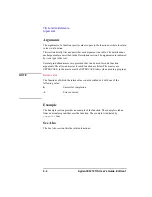
Page 26: ...l pre defined macros are provided that can be used for some function arguments The allowed macros for each function are listed The macros are UPPERCASE so the macro must be UPPERCASE letters when used in a program NOTE Return value The functions of which the return value is not described exit with one of the following value 0 Successful completion 1 Error occurred Example The Example section provi...

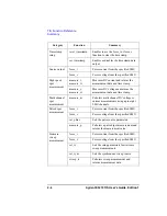
Page 27: ...ection to the Agilent E5270 Reset init_system Initializes the Agilent E5270 Query error_info Returns a TIS error number and an error message string port_status port_status_t Returns the status of the specified port and time stamp status_miv Returns the status of the data measured by sweep_iv or sweep_miv function and time stamp Channel Port control connect_pin Enables source measurement channel di...

Page 28: ... DC voltage and returns the measurement data and time stamp Multi channel spot measurement measure_m Performs multi channel DC voltage or current measurements using up to eight SMU channels Pulsed spot measurement force_i Forces current from the specified SMU force_v Forces voltage from the specified SMU set_pbias Sets the pulse source parameters measure_p Performs a pulsed spot measurement and re...

Page 29: ...measurement force_i Forces current from the specified SMU force_v Forces voltage from the specified SMU set_piv Sets the setup parameters for pulsed sweep measurements set_sync Sets the synchronous sweep source sweep_iv Performs pulsed sweep measurement and returns measurement data Staircase sweep with pulsed bias measurement force_i Forces current from the specified SMU force_v Forces voltage fro...

Page 30: ...p parameters for breakdown voltage measurement measure_bdv Performs breakdown voltage measurement and returns measurement data Leakage current measurement force_i Forces current from the specified SMU force_v Forces voltage from the specified SMU set_ileak Sets the setup parameters for leakage current measurement measure_ileak Performs leakage current measurement and returns measurement data Categ...

Page 31: ...ption SMU1 20001 Specifies SMU installed in the Agilent E5270 For the Agilent E5272A and E5273A SMU1 always specifies the left side SMU viewed from the front SMU3 to SMU8 are not available For the Agilent E5270A SMU1 always specifies the SMU installed in a slot closest to the slot 1 SMU2 and followings specify SMU following to the previous one where slot 1 is the left top slot and slot 8 is the ri...

Page 32: ... nA 1 nA 50 fA 10 fA b b The resolution of returned value is range value 1000000 1 15 nA range 11 5 nA 10 nA 500 fA 10 fA 11 5 nA range 115 nA 100 nA 5 pA 100 fA 115 nA range 1 15 mA 1 mA 50 pA 1 pA 1 15 mA range 11 5 mA 10 mA 500 pA 10 pA 11 5 mA range 115 mA 100 mA 5 nA 100 pA 115 mA range 1 15 mA 1 mA 50 nA 1 nA 1 15 mA range 11 5 mA 10 mA 500 nA 10 nA 11 5 mA range 115 mA 100 mA 5 mA 100 nA 11...

Page 33: ...V 5 mV 100 mV 100 V range 200 V for HPSMU 200 V 10 mV 100 mV range value Output Range Output Value a a Setting resolution is determined by actual output range used to force the output voltage Setting Resolution Maximum Compliance MPSMU HPSMU 0 range 2 V 2 V 0 V 2 V 100 mV 200 mA 1000 mA 2 V range 20 V 20 V 0 V 20 V 1 mV 200 mA 1000 mA 20 V range 40 V 40 V 0 V 20 V 2 mV 200 mA 500 mA 20 V V 40 V 50...

Page 34: ...e 100 nA 100 nA 0 I 100 nA 5 pA 100 V 200 V 100 nA range 1 mA 1 mA 0 I 1 mA 50 pA 100 V 200 V 1 mA range 10 mA 10 mA 0 I 10 mA 500 pA 100 V 200 V 10 mA range 100 mA 100 mA 0 I 100 mA 5 nA 100 V 200 V 100 mA range 1 mA 1 mA 0 I 1 mA 50 nA 100 V 200 V 1 mA range 10 mA 10 mA 0 I 10 mA 500 nA 100 V 200 V 10 mA range 100 mA 100 mA 0 I 20 mA 5 mA 100 V 200 V 20 mA I 50 mA 40 V 50 mA I 100 mA 20 V 100 V ...

Page 35: ...E5270 This function terminates the software connection to the Agilent E5270 and deallocates system resources This function must be executed to close the instrument handle when the program is done using the Agilent E5270 Synopsis int close_E5270 void Example close_E5270 See Also open_E5270 ...

Page 36: ...e Agilent 4070 pin 1 to 48 specify the switching matrix pin numbers pin 49 specifies the connector for chuck connection Example int err err connect_pin SMU1 12 See Also disconnect_all Item Range Restrictions Description port Specify channel to enable Available port values are 0 GNDU SMU1 to SMU8 or values shown in Table 2 2 port 0 clears the port assignment for the specified pin pin This item is n...

Page 37: ... Zero Output State Item Range Restrictions Description port Specify channel to be set to the zero output state by using the port address or a pin number that is assigned to the port by the connect_pin function Available port values are 0 to 49 SMU1 to SMU8 or values shown in Table 2 2 on page 2 9 port 0 sets all ports to the zero output state Setup Item Setting Value Output Mode Voltage output Out...

Page 38: ...t_all This function disables all channels and clears all assignments set by the connect_pin functions This function is equivalent to the connect_pin 0 0 function and is recommended for better program readability Synopsis int disconnect_all Example int err err disconnect_all See Also connect_pin ...

Page 39: ...unction is executed both error numbers are set to 0 and the error message string is set to a null string No value is returned to the function itself even if an error occurs Example error_info error_number error_msg Item Range Restrictions Description errn Pointer to an integer array in which to return the TIS error number errn 0 TIS error number errn 1 CMS DVM or PGU error number that is meaningfu...

Page 40: ...t output range Numeric expression A See Table 2 6 on page 2 12 0 2 to 0 2 for MPSMU or 1 0 to 1 0 for HPSMU a To use the auto ranging mode set 0 b a SMU uses limited auto ranging mode The SMU forces current at the specified range if the specified range can force the current If not the SMU ranges up to range that can force the current b SMU forces current at the lowest range that can force the curr...

Page 41: ...own in Table 2 6 on page 2 12 lower output range has better setting resolution But a lower output range may increase settling time If you specify a value that is not an exact output range listed in Table 2 6 on page 2 12 the range is used according to the table For example if you set current and range to 11 mA the 100 mA range is used Example int err err force_i SMU1 i_ds1 i_ds2 2 0 ...

Page 42: ...re 1 to 49 SMU1 to SMU8 and values shown in Table 2 2 on page 2 9 voltage Value of voltage to force Numeric expression V See Table 2 5 on page 2 11 100 to 100 for MPSMU or 200 to 200 for HPSMU range Voltage output range Numeric expression V See Table 2 5 on page 2 11 100 to 100 for MPSMU 200 to 200 for HPSMU a To use the auto ranging mode set 0 b a SMU forces voltage by using the range that covers...

Page 43: ...tion 1 2 21 TIS Function Reference init_system init_system This function initializes the Agilent E5270 Execute the init_system function before executing any other TIS function Synopsis int init_system Example if init_system 1 error_rep ...

Page 44: ...tage measurement If the interval is set to BDV_INTVL_LONG the gradient is calculated after every 10 voltage measurements When the interval is set to BDV_INTVL_SHORT a slew rate of less than 1 V ms causes an error status BDV_TOO_SLOW When the interval is set to BDV_INTVL_LONG a slew rate of less than 0 1 V ms causes an error status BDV_TOO_SLOW The time out for the quasi pulsed measurement is set t...

Page 45: ...e which status was returned Description 0 BDV_NORMAL The quasi pulsed measurement ended normally 1 BDV_COMP_OTHER Another unit reached compliance 2 BDV_CURRENT_LOW Breakdown voltage measurement failed because current did not reach breakdown current within the stop voltage specified by set_bdv function 3 BDV_OSC This unit is oscillating 4 BDV_OVERFLOW Measurement overflow occurred while monitoring ...

Page 46: ...to return the measurement value range Current measurement range Numeric expression A See Table 2 3 on page 2 10 0 2 to 0 2 for MPSMU or 1 0 to 1 0 for HPSMU a To use the auto ranging mode set 0 b If the SMU is I_SOURCE mode set any value c a SMU uses limited auto ranging mode The SMU uses the specified range if possible but changes to a higher range if not possible b SMU uses the range that gives ...

Page 47: ...asurement resolution but may increase measurement time because of additional ranging and wait times NOTE To Clear Timer Count Execute the reset_timestamp function Then the timer count is not cleared Execute the force_i or force_v function Then the timer count will be cleared Once the force_i or force_v function is executed the effects of the reset_timestamp function will be disabled Example if mea...

Page 48: ...et to ILEAK_INTVL_SHORT a slew rate of less than 1000 V s 1 V ms causes an error status ILEAK_TOO_SLOW When the interval is set to ILEAK_INTVL_LONG a slew rate of less than 100 V s 0 1 V ms causes an error status ILEAK_TOO_SLOW The time out is set to 3 seconds for ILEAK_INTVL_SHORT mode and 12 seconds for ILEAK_INTVL_LONG mode Item Range Restrictions Description port Specify current measurement ch...

Page 49: ...e the associated macros in your program to determine which status was returned Condition 0 ILEAK_NORMAL The quasi pulsed measurement ended normally 1 ILEAK_COMP_OTHER Another unit reached compliance 2 ILEAK_COMP This unit reached compliance 3 ILEAK_OSC This unit is oscillating 4 ILEAK_OVERFLOW Measurement overflow occurred while monitoring the output voltage or measuring the leakage current 6 ILEA...

Page 50: ... double meas_vals n ranges n time_stamps n Arguments Item Range Restrictions Description n Specify how many ports will perform measurement The size of the ports meas_vals ranges and time_stamps arrays must be n n can be from 1 to 8 ports Specify a pointer to an integer array that contains the measurement channels This array must have n elements The array should contain the port addresses or pin nu...

Page 51: ... Also measure_i measure_it measure_v measure_vt and reset_timestamp Item Range Restrictions Description ranges Specify a pointer to double array that contains the measurement range for each channel This array must have n elements Specify values in ranges array in order that corresponds to elements of the ports array See measure_i measure_it on page 2 24 for current measurement range See measure_v ...

Page 52: ...nt is executed and this function just triggers to force the pulsed bias that is set by set_pbias statement mode Specify whether to perform a voltage or current measurement Use one of the following macros or values V_MEAS 1 Voltage measurement mode The channel must be a current source I_MEAS 2 Current measurement mode The channel must be a voltage source value Specify a pointer to a double variable...

Page 53: ...pulsed spot measurement always uses high speed ADC And the number of averaging samples is set to 1 The resolution of returned value is measurement range value 20000 Example int err double current err set_pbias SMU1 V_SOURCE 20 3 15 0 4 1 0 5 1E 3 err measure_p SMU1 I_MEAS current 1E 3 See Also set_pbias ...

Page 54: ...ch to return the measurement result range Voltage measurement range Numeric expression V See Table 2 4 on page 2 11 100 to 100 for MPSMU or 200 to 200 for HPSMU a To use the auto ranging mode set 0 b If the SMU is V_SOURCE mode set any value c a SMU uses limited auto ranging mode The SMU uses the specified range if possible but changes to a higher range if not possible b SMU uses the range that gi...

Page 55: ...easurement resolution but may increase measurement time because of additional ranging and wait times NOTE To Clear Timer Count Execute the reset_timestamp function Then the timer count is not cleared Execute the force_i or force_v function Then the timer count will be cleared Once the force_i or force_v function is executed the effects of the reset_timestamp function will be disabled Example if me...

Page 56: ...o the status variable This status variable remains unchanged until the next measurement Item Range Restrictions Description port Specify measurement channel by using the port address or a pin number that is assigned to the port by the connect_pin function Available port values are 1 to 49 SMU1 to SMU8 GNDU and values shown in Table 2 2 on page 2 9 status Specify a pointer to integer variable in wh...

Page 57: ...n will be disabled Example if port_status SMU1 smu_status 1 error_rep Status Code a a One of the above integers is returned to status You can also use the associated macros in your program to determine which status was returned Description 0 NORMAL_MEAS b b The returned status of a port that has not performed measurement is always NORMAL_MEAS normal Normal 1 DCS_COMP_OTHER Another unit has reached...

Page 58: ...nstr_desc Specify the GPIB interface and address of the Agilent E5270 For example instr_desc GPIB0 17 INSTR specify the Agilent E5270 that is the address 17 on GPIB0 interface err_detect Specify automatic instrument error checking ON or OFF by using the following macros or values ERR_DETECT_OFF 0 Disables error checking ERR_DETECT_ON 1 Enables error checking If error checking is enabled the VXIplu...

Page 59: ...le the time data output execute the set_timestamp function Effects of the reset_timestamp and set_timestamp function will be disabled by the init_system function Synopsis int reset_timestamp void Example reset_timestamp See Also set_timestamp NOTE To Clear Timer Count Execute the reset_timestamp function Then the timer count is not cleared Execute the force_i or force_v function Then the timer cou...

Page 60: ...ouble value Arguments Item Range Restrictions Description adc Specify the high speed ADC or high resolution ADC You can use the following macros or values PERCH_ADC 0 High speed ADC REF_ADC 1 High resolution ADC mode Specify the integration mode See Table 2 11 value Specify integration time or number of averaging samples See Table 2 11 autozero a a If adc is PERCH_ADC this is dummy parameter Set a...

Page 61: ...always 128 If you set value the value is ignored 3 INTEG_LONG Specify value in the following formula Number of samples 128 value Available values are 1 to 100 value 0 sets the number of samples to 128 16 High resolution ADC 0 INTEG_MANUAL Specify the integration time 80E 6 to 10 16E 3 sec Or specify the number of power line cycles for integration by ADC 1 to 100 value 0 sets the integration time t...

Page 62: ... V See Table 2 5 on page 2 11 100 to 100 for MPSMU or 200 to 200 for HPSMU start stop Specify the start voltage or stop voltage of the search Numeric expression V See Table 2 5 on page 2 11 The difference between the start voltage and stop voltage must be 10 V or more 100 to 100 for MPSMU or 200 to 200 for HPSMU current Specify the breakdown current Numeric expression A See Table 2 5 on page 2 11 ...

Page 63: ...t will increase rapidly and reach the current compliance current quickly and the rate of voltage change will be slower And when the rate becomes less than half of the initial rate the SMU waits the delay time and performs voltage measurement After that the SMU output voltage is set to start The measurement result is returned to the voltage variable specified by the measure_bdv function If breakdow...

Page 64: ...o 49 SMU1 to SMU8 and values shown in Table 2 2 on page 2 9 range SMU voltage output range Numeric expression V See Table 2 5 on page 2 11 100 to 100 for MPSMU or 200 to 200 for HPSMU voltage Specify the voltage at which the leakage current is measured Numeric expression V See Table 2 5 on page 2 11 The difference between voltage and start must be 10 V or more 100 to 100 for MPSMU or 200 to 200 fo...

Page 65: ...e SMU output voltage is set to start The measurement result is returned to the current variable specified by the measure_ileak function This function is effective for a low leakage measurement with high voltage The measurement voltage voltage is automatically detected and measurement is performed soon so high voltage will not be applied to the DUT for a long time This will prevent the DUT from dam...

Page 66: ...2 44 Agilent E5270 TIS User s Guide Edition 1 TIS Function Reference set_ileak Figure 2 2 Quasi pulsed Wave form for Leakage Current Measurement See Also measure_ileak ...

Page 67: ... step values in this figure are determined as shown in Table 2 12 and Table 2 13 Table 2 12 start stop step values for linear sweep Item Description start value resolution depends on the output range setting stop value a a The actual stop value may be slightly different from the specified value Because the step value may be rounded off depending on the setting resolution See Table 2 5 on page 2 11...

Page 68: ...ared by the init_system function that initializes the Agilent E5270 Item Description start value resolution depends on the output range setting stop value a a The actual stop value may be slightly different than the specified value Because the step value may be rounded off depending on the setting resolution See Table 2 5 on page 2 11 and Table 2 6 on page 2 12 for setting resolution stop start 1E...

Page 69: ...d values shown in Table 2 2 on page 2 9 sweep_mode Specify sweep mode by using the following macros or values LINEAR_V 1 Linear voltage single sweep LINEAR_I 2 Linear current single sweep LINEAR_V_DBL 3 Linear voltage double sweep LINEAR_I_DBL 4 Linear current double sweep LOG_V 1 Logarithmic voltage single sweep LOG_I 2 Logarithmic current single sweep LOG_V_DBL 3 Logarithmic voltage double sweep...

Page 70: ...ows after the hold time before starting measurement 0 to 655 35 0 01 resolution delay Specify the delay time to keep each step value before starting measurement Numeric expression s 0 to 65 535 0 0001 resolution compliance Specify a current or voltage compliance value depending on the sweep_mode Numeric expression For voltage sweep 0 2 to 0 2 for MPSMU or 1 0 to 1 0 for HPSMU in A See Table 2 6 on...

Page 71: ...pplied to the port Numeric expression W 0 001 to 4 for MPSMU or 0 001 to 20 for HPSMU 0 001 resolution To disable the power compliance set power_compliance 0 stop_mode Specify automatic sweep abort function ON or OFF by using the following macros or values COMP_CONT 1 Disables the function COMP_STOP 2 Enables the function If you set power_compliance to non zero value stop_mode setting is ignored H...

Page 72: ...ge is not changed when the sweep measurement is being executed NOTE power_compliance and compliance If you specify power_compliance 0 available voltage compliance or current compliance value depends on the maximum sweep output value start or stop See Table 2 6 on page 2 12 and Table 2 5 on page 2 11 for maximum compliance value If you specify non zero power_compliance value the SMU changes the cur...

Page 73: ... abort conditions occurs If you set power_compliance to non zero value stop_mode is ignored The sweep stops when one of the sweep abort conditions occurs or the output reaches power compliance After sweep was aborted the sweep_iv sweep_miv or status_miv function returns data shown in the following example that an abort condition occurs at Step N a X will be a status code that indicates a sweep abo...

Page 74: ...e sweep with pulsed bias measurement as shown in Figure 2 5 To start pulsed spot measurements execute this function and then measure_p function The SMU forces the base value waits the hold time and forces a pulse During the period the SMU cannot force next pulse The SMU can force next pulse in the period given by the following t1 value t1 MAX t hold period where t is time from beginning of pulse t...

Page 75: ...e timing set by this function See Figure 2 5 NOTE Functions that disable the set_pbias settings If the set_iv function is executed after this function the set_pbias settings will be cleared and the set_iv settings will be effective If program contains this function and the set_piv function the set_pbias settings will not be effective and the set_piv settings will be effective If the disable_port f...

Page 76: ...ues V_SOURCE 1 Voltage output mode I_SOURCE 2 Current output mode range Source output range Numeric expression For voltage pulse 100 to 100 for MPSMU or 200 to 200 for HPSMU in V See Table 2 5 on page 2 11 For current pulse 0 2 to 0 2 for MPSMU or 1 0 to 1 0 for HPSMU in A See Table 2 6 on page 2 12 To use the auto ranging mode set range 0 base peak Specify the pulse base and peak values of the vo...

Page 77: ...0 msec for width 100 ms If you do not specify period 0 sec is set hold Specify time to wait after trigger before forcing peak value Numeric expression s 0 to 655 35 0 01 resolution compliance Specify a current or voltage compliance value depending on the mode Numeric expression For voltage sweep 0 2 to 0 2 for MPSMU or 1 0 to 1 0 for HPSMU in A See Table 2 6 on page 2 12 For current sweep 100 to 1...

Page 78: ...e that includes both base and peak values If you set non zero range value for the voltage pulse source output range is fixed to specified range If you set non zero range value for the current pulse source output range is determined by limited auto ranging mode The SMU forces the current pulse at the specified range if the specified range can force both base and peak value If not the SMU ranges up ...

Page 79: ...parameters for pulsed sweep measurements that are started by the sweep_iv function The setup parameters pulse base voltage or current start stop hold width and period determine the pulsed sweep measurement conditions as shown in Figure 2 6 and Figure 2 7 Figure 2 6 Single Pulsed Sweep Figure 2 7 Double Pulsed Sweep ...

Page 80: ...t_piv port sweep_mode range base start stop number width period hold compliance stop_mode int port sweep_mode number stop_mode double range base start stop double width period hold compliance Item Description start value resolution depends on the set voltage or current range stop value a a The actual stop value may be slightly different from the specified value Because the step value may be rounde...

Page 81: ...ression For voltage pulse 100 to 100 for MPSMU or 200 to 200 for HPSMU in V See Table 2 5 on page 2 11 For current pulse 0 2 to 0 2 for MPSMU or 1 0 to 1 0 for HPSMU in A See Table 2 6 on page 2 12 To use the auto ranging mode set range 0 base start stop Specify the pulse base start and stop values of the voltage or current being forced If mode is I_SOURCE base and start stop must have the same po...

Page 82: ...umeric expression For voltage sweep 0 2 to 0 2 for MPSMU or 1 0 to 1 0 for HPSMU in A See Table 2 6 on page 2 12 For current sweep 100 to 100 for MPSMU or 200 to 200 for HPSMU in V See Table 2 6 on page 2 12 A macro REMAIN is also available If you set REMAIN the compliance value is automatically set to the last compliance value if the output mode of this channel was same as the last output mode Or...

Page 83: ...MU oscillates If you set stop_mode to COMP_STOP the sweep stops when one of the sweep abort conditions occurs After sweep was aborted the sweep_iv sweep_miv or status_miv function returns data shown in the following example that an abort condition occurs at Step N a X will be a status code that indicates a sweep abort condition Step measure or meas_vals source sync statuses times 1 measured data o...

Page 84: ...to specified range If you set non zero range value for the current pulse source output range is determined by limited auto ranging mode The SMU forces the current pulse at the specified range if the specified range can force base start and stop If not the SMU ranges up to range that can force base start and stop Example int number double vbase vstart vstop width period hold comp double meas1 101 s...

Page 85: ...t set the filter to ON which reduces overshoot voltage or current in the output of the SMU Example set_smu_ch SMU1 REF_ADC FILTER_ON See Also set_adc Item Range Restrictions Description port Specify SMU by using the port address or a pin number that is assigned to the port by the connect_pin function Available port values are 1 to 49 SMU1 to SMU8 and values shown in Table 2 2 on page 2 9 port 0 is...

Page 86: ... measurement is started by the sweep_iv function The output mode of the synchronous sweep source is automatically set to the same sweep_mode linear or logarithmic VS or IS and double or single as the primary sweep port set by the set_iv or set_piv function The synchronous sweep source always performs staircase sweep output even if the primary sweep source performs pulsed sweep output Note that you...

Page 87: ...ow mode POS_SYNC start value offset ratio start of primary sweep source stop value offset ratio stop of primary sweep source mode NEG_SYNC start value offset ratio start of primary sweep source stop value offset ratio stop of primary sweep source where offset value is not effective for the logarithmic sweep Specify mode offset and ratio values so that the synchronous sweep source start and stop va...

Page 88: ... to 1 0 for HPSMU in A See Table 2 6 on page 2 12 For current sweep 100 to 100 for MPSMU or 200 to 200 for HPSMU in V See Table 2 5 on page 2 11 A macro REMAIN is also available If you set REMAIN the compliance value is automatically set to the last compliance value if the output mode of this channel was same as the last output mode Or the compliance value is set to 100 mA if the last output mode ...

Page 89: ... time stamp data To get the time stamp data the set_timestamp function must be executed before these functions For sweep measurement the set_timestamp function must be executed before sweep_iv or sweep_miv function Synopsis int set_timestamp on int on Arguments NOTE To Clear Timer Count Execute the reset_timestamp function Then the timer count is not cleared Execute the force_i or force_v function...

Page 90: ...set_timestamp function will be disabled Item Range Restrictions Description n Specify the number of measurement channels 1 to 8 ports Specify a pointer to an integer array that contains the SMU port addresses or pin numbers that are assigned to the ports by connect_pin functions Available ports values are 1 to 49 SMU1 to SMU8 and values shown in Table 2 2 on page 2 9 statuses Specify a pointer to ...

Page 91: ...set_piv and synchronous sweep source set by set_sync Also a pulse source may be used if set_pbias function is entered after the set_iv function NOTE To get the status data This function does not return status data Use status_miv function to get the statuses of each measurement points or port_status function to get the status of last measurement point Synopsis int sweep_iv port mode range measure s...

Page 92: ...t measurement 0 2 to 0 2 for MPSMU or 1 0 to 1 0 for HPSMU in A See measure_i measure_it on page 2 24 To use the auto ranging mode set range 0 measure Specify a pointer to a double array in which to return the measurement results source Specify a pointer to double array in which to return the sweep source values which are determined by set_iv or set_piv function If these values are not necessary s...

Page 93: ...eturn status data Use status_miv function to get the statuses of each measurement points or port_status function to get the status of last measurement point Synopsis int sweep_miv n ports ranges meas_vals source sync int n ports n double ranges n meas_vals nx source x sync x Where x is the number of steps specified in set_iv function For double sweep x should be 2x Arguments Item Range Restriction...

Page 94: ...t to the set_iv function Measurement results are returned to meas_vals array in order that corresponds to elements in the ports array source Specify a pointer to a double array in which to return the sweep source data which is determined by set_iv This array must have number elements for a single sweep and 2 number elements for a double sweep Where number is the number of sweep steps set to the se...

Page 95: ...miv Example int err int n 3 ports 3 double ranges 3 meas_vals 303 sweep 101 ports 0 8 ports 1 12 ports 2 16 ranges 0 0 0 ranges 1 0 0 ranges 2 0 0 err set_iv SMU1 LINEAR_V 0 0 5 101 err sweep_miv n ports ranges meas_vals sweep NULL See Also set_iv set_sync sweep_iv status_miv ...

Page 96: ...ired to use the VXIplug play driver for Agilent E5270 The driver can be used in a program by using the session ID Synopsis ViSession vi_E5270 void Example The following example sends the CAL command to the Agilent E5270 by using the e5270_cmd function that is a function of the Agilent E5270 VXIplug play driver e5270_cmd vi_E5270 CAL ...

Reviews: